|
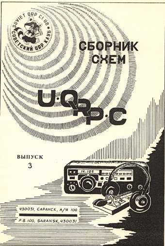
At QRP rubric at Antentop 01- 2005 I use stuff from
old Soviet QRP magazine published by the U- QRP- C at 1991. It
was named "U- QRP-
C. Reference Book- #3," you
can see its cover at the right. The schematics, which were published
there, are very interesting till now.
The simple QRP
TX used two FETs
was published at "U-
QRP- C. Reference Book- #3," page 4. I have
done the TX, it worked pretty well! I have tried it in several
ways. Pair low power FETs (300 MHz, 300 mWt) did very good job,
near 200- 300 mWts output without problem. I put in parallel up
to 5 the same transistors (instead output transistor), it gives
near 1 watts, the transistors were without a heat sink. Of course,
goog results were obtained at first FET (300 mWt, 300 MHz), second
MOS, 300 MHz, 3 watts. I have near 2 watts at 24 Volts.
If instead C2 you use a variable
capacitor, you can use quartz for 3500 or 1750 kHz. Of course,
the transmitter works good at another bands, for 30, 20, 15 and 10 meters, however,
the power is dropped. At 80 and 160 meters the TX has good power
and clean tone. I did experiments with the TX and RF- generator,
I removed the quartz, and put output of the generator to clips
'VFO.' So, I have got very nice small TX, that worked very good.
Data: L1= L2: diameter 30 mm, winding length 35 55,
15 turns, L2 tap from middle, L3 3 turns above center L2.
|

|


