

|
|
 |
 |
 |
|
|
Antentop is FREE e-magazine devoted to Antennas and Amateur Radio an
Special page devoted to
Shunt Vertical Universal HF Antenna

Custom Search
|
ANTENTOP-
02- 2004, # 006 |
Shunt
Vertical Universal HF Antenna |
|
|
|
||
|
|
||
|
|
||
|
Field
universal antenna RV3DA (see pp.:24-
35 of ANTENTOP- 02- 2004) works well even at a bad
grounding. To hammer into the ground a metal rod in 1 meter length
is enough for the grounding. Installation of the antenna takes
a little time, it is another its advantage.However, if there is
an opportunity to provide a good ground, and there is some free
time to spend of for installation of an antenna, it is possible
to use a Shunt Vertical Universal HF
Antenna . |
Igor
Grigorov, Rk3ZK
Universal
HF Antenna has a gain less then universal antenna RV3DA. It is
possible to do a design of the |
|
|
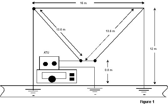
Figure
1 shows the schematic of the Shunt Vertical Universal HF Antenna.
A detailed description of the theory of a Shunt Vertical Universal
is given at reference [1].
Apparently,
the circuit of the antenna only a bit differs from field universal
antenna RV3DA. The differences are: the loop is isolated from
the ground, its terminals are shortened, shunts go down from two
tops of the triangle loop to the ground. To ground shunts is possible
as to universal antenna RV3DA it is done, i.e., a metal rod in
1 meter length is enough for the grounding. Of course, several
counterpoises (three and more) in length 0f 5 meters (and more)
help to improve the antenna operation. Counterpoises can lay on
a surface of the ground. Shunt
Vertical Universal HF Antenna radiates mainly vertical radiation.
It is required to use the antenna at woodless surrounding or big
losses of high-frequency energy will be. Please, take attention
Shunt Vertical |
Shunt
Vertical Universal HF Antenna so, that this one can be easy turned
to the field universal antenna RV3DA. Below
given diagram directivity for the antenna obtained with help of
free antenna program MMANA (MININEC based). Left diagram is a
section of the volumetric diagram directivity of plane X-Y at
a zenith corner of the maximum radiation. The right diagram is
section of the volumetric diagram directivity of plane X- Z. Also
at the right down corner of the pictures is a table with antenna
impedance. Please, take attention to the data, you can do decision
how you ATU does match of the Reference: 1.
Aizenberg G. Z. Antennas of Short Waves.: Moscow, "Radio
i Svyaz", 1985. 73!, de
RK3ZK |
|
|
|
|
|
|
|
||
|
|
||
|
|
|
|
|
|
Page
36 |
|
36 37 38 39 40 41 42 43 44 45 46
 |
 |
 |
 |
Just for Fun:

Powered byIP2Location.com
Thanks for your time!
Last Updated:
February 23, 2020 20:40