


|
|
 |
 |
 |
|
|
Antentop is FREE e-magazine devoted to Antennas and Amateur Radio an
Special page devoted to
Something about ATU

Custom Search
|
ANTENTOP-
01- 2004, # 005 |
Something
about ATU |
||
|
|
|||
|
|
|||
|
|
|
||
|
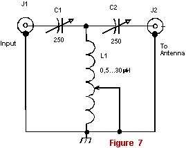
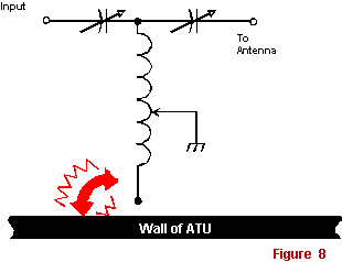
The "cold" end of L1 should be grounded or isolated carefully
from the metal case of ATU. Otherwise you probably will have strong
arc between the ungrounded end of L1 and a wall of the ATU, as
it is shown in Fig. 8. C1 and C1 should be very qualitative with
aerial or vacuum dielectric. The clearance between plates of capacitors
should be not less than 2-mm/ to 200-W bypass power. Stray capacitance
of C1 and C2 to the metal case of ATU should be no more than 25-pF,
otherwise the efficiency at 24-28-MHz drop. Figure 8
Arcing inductor If you want to connect symmetrical
antennas feeding through symmetrical ladder lines to the T- Matching
Unit, use symmetrical transformer 1:4 or 1:6. BTW, many of symmetrical
antennas, feeding through ladder lines have large reactive component,
which bad to transformation by simple transformers 1:4 or 1:6.
The T - Matching Unit suppress harmonics up to 10-15 dB. |
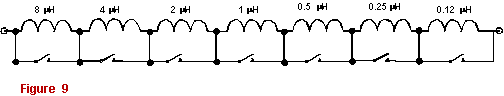
T - Matching Unit with a �digital� inductor L1 has to have slide contact to operate the MU in proper way. Sometimes,
even extra half of a turn influences to the matching. It restricts
usage of an inductor with taps, or demands personal selection
taps for real antenna, that certainly, restricts possibilities
"tap" MU. Simple decision on this problem by W3TS made,
he offered a "digital" inductor that Fig.
9 shows. Really, it is possible with the help of several
switches very fine to tune needed inductance. Electronic relays
with special chips allow realize automatic ATU. Military also
use the method at their automatic ATU. T - Matching Unit with mirror parts For practical design of any ATU it is not conveniently to have two capacitors
insulated from the ground. AEA corporation (USA) does the MU as
Fig. 10 shows.
You can see that they changed C to L. Really, schemes of MU figured
in Fig. 7 and Fig.
10 are equivalent. |
||
|
|
|||
|
|
|
||
|
|
Page 43 |
||

 |
 |
 |
 |
Just for Fun:

Powered byIP2Location.com
Thanks for your time!
Last Updated:
February 23, 2020 22:06