


|
|
 |
 |
 |
|
|
Antentop is FREE e-magazine devoted to Antennas and Amateur Radio an
Special page devoted to
Something about ATU

Custom Search
|
ANTENTOP-
01- 2004, # 005 |
Something
about ATU
|
||
|
|
|||
|
-
Dummy loads R1, R2 and R3, that help us to monitor
how Matching Unit and SWR- meter (HF-bridge) do work:
-
S1 and S2 for proper connection of the above mentioned
parts;
-
J1 and J2 for transmitter and antenna connection. So, how the ATU does work? S1 at "Bypass" position does connection of the transmitter
to S2. S2 does connection or to antenna, or to Dummy Loads R2
(50 Ohms) or R3 (600 Ohms). So, at good 50-Ohms antenna the transmitter
works straight on the antenna, also is possibility to load the
transmitter on 50-Ohms Dummy Load for
a tuning of the transmitter or checking of the SWR- meter. S1 at "Tune" position does connection of the transmitter through
inner HF-bridge and Matching Unit to S2. So, it is possible to
tune the Matching Unit or on to real antenna (S2 in position Ant)
or check how the Matching Unit can tune to 50-Ohms (S2 in position
Load 1) or 600-Ohms (S2 in position Load 2) load. When you have
your antenna tuned, switch S1 in position "Operate"
and just work in the ether. You can see, it is possible to use or SWR- meter or HF-bridge for tuning
the MU on to real load. As it is visible from this scheme the degree of the matching of the transmitter
with used antenna depends only on used Matching Unit. Let's see
what our Matching Unit can contain. Classical
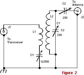
Matching Unit One of most effective Matching Units is shown on Fig. 2. This scheme was widely used by the radio
amateurs from early 30s till recently days. As it is visible from
Fig. 2, the end stage of the transmitter is connected
through coupling coil L1 and coupling capacitor C1. L2 and C2
is tuned to resonance to input signal. C3 does coupling with
the load (antenna).
|
As usual, L1 has from ¼ to 1/6 from amount of turns of L2. L1
is winded in lower part of L2. L1 should be unbound from L2 by
any qualitative isolation. In some designs of the MU,
L1 is isolated by means of air. The transmitter is coupled
to the antenna only by magnetic field, so the end stage of the
transmitter is protected from a lightning. Resonance circuit kills
harmonics. The Classical Matching Unit does well match a load
from 10 to 1000 Ohms with end stage of transmitter in 50 or 75-Ohm
impedance. C1 should have maximum of capacity up to 1500-pF at operation through
1,8- 28 MHz, and 500-pF would be enough
for operation through 3.5- 28 MHz. If L1 has optimal number of
turns the C1 is not necessary at all. C2 and C3 should have the
greatest possible clearance between their plates. At constant parameters of L1 and L2 the Classical Matching Unit works
with high efficiency only in two multiple amateur HF - ranges,
for example, 1,8 and 3,5 MHz, 7 and 14 MHz and so on. At others
ranges efficiency is dropped. Old Classical Matching Unit had
plug-in coils for all amateur range for keeping the efficiency
at high level. L2 should be placed as far as possible from
metal walls of the cabinet of the ATU. To tune the MU is very simple. At first, C1 has the maximum capacity, C2 and C3 have minimum capacity. Then, with help
of C2 do tune resonance circuit L2C2 in the resonance to working
frequency, then C3 does optima matching with the antenna. After
that once more time do tuning C2 and C1. It is necessary to say,
that after final tuning of the MU C3 has to have the greatest
capacity as it is possible. Advantages of the MU are following. It does not require too careful manufacture
of L1 and L2. The system ensures high efficiency, up to 80 percents.
Tuning is done with two capacitors C2 and C3. The lacks are that
for high efficiency in the matching unit it is necessary to use
one spool to two multiple ranges, and one variable capacitor insulated
from case of an ATU. Classical
Matching Unit with a symmetrical output Recently symmetrical
antennas with a symmetrical feeder are applied seldom, but some
decades ago it was a usual matter. Classical Matching Unit with
symmetrical output is shown on Fig.
3. In scheme shown in Fig.
3 a RF- voltage for antenna - feeder system is removed
symmetrically from both ends of L2, and it is only difference
from the scheme shown in Fig. 2.
In practical design L1 should be disposed symmetrically concerning
resonance spool L2. Twins capacitors C2.1 and C2.2 should have
one axe. It is as well as to C3.1 and C3.2. |
||
|
|
|
||
|
|
Page 41 |
||
 |
 |
 |
 |
Just for Fun:

Powered byIP2Location.com
Thanks for your time!
Last Updated:
February 23, 2020 22:00