|
|
 |
 |
 |
|
|
Antentop is FREE e-magazine devoted to Antennas and Amateur Radio an
Special page devoted to
4-Ovals Antenna for 430- 440 -MHz

Custom Search
|
ANTENTOP-
03- 2003, # 004 |
4-Ovals
Antenna for 430- 440 -MHz
|
||
|
|
|||
|
Igor, UA6HJQ, ua6hjq@mail.ru |
|||
|
|
|||
|
I need a good universal antenna for repeaters working
at the 70-cm range, packet radio and for routine work. Such antenna
must be satisfy the follow characteristics: 1.
Real Gain 9-10-dB. 2. Low SWR
at 430-440- MHz. 3. Wide forward
lobel. |
|
||
|
4. Unpretentiousness to close located subjects. 5. Simplicity in manufacturing and adjustments. 6. Possibility to create phased
systems on the basis of the antennas. 7. 50- Ohm coaxial cable feeding.
|
8. Stability to heavy icing and to
winds in 10-20 meters per second.. 4 Ovals Antenna
responded all of the conditions.
Why an oval? At first, from the antenna theory we know that an
oval radiates energy a little bit more effectively than a square.
At the second, in practical, it is more easy to do an oval then
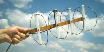
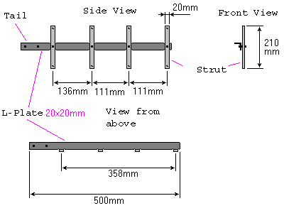
a square.. So choose the OVAL! Figure
1 shows a design of the |
||
|
Figure 1
|
|||
|
|
|||
|
antenna. Boom is made of iron L-plate 25x25-mm.
All the four ovals are fastened to the boom by struts made of
insulation stuff such as tree, hetinax, etc. Antenna is fastened
by the tail, that is behind the struts. Perimeter
of elements (ovals): Reflector- 727-mm. (-20-mm for soldering).
Driven Element: 653-mm
(+10-mm distance for a RF socket). |
Director-I:
649-mm. (-20 mm). Director-
II: 639-mm. (-20-mm). Figure
2 shows the design of the Driven Element.
RF socket is soldered directly by the ends of the oval. Three
holes is drilled at each strut. One holes
is in the center for fastened the strut to the boom, two holes
are at the ends for bimetal oval. Antenna reflectors and directors
have the same design as the Driven Element
only difference is its ends soldered together. |
||
|
|
|
||
|
|
Page 69 |
||
69 70
 |
 |
 |
 |
Just for Fun:

Powered byIP2Location.com
Thanks for your time!
Last Updated:
March 1, 2020 20:24