

|
|
 |
 |
 |
|
|
Antentop is FREE e-magazine devoted to Antennas and Amateur Radio an
Special page devoted to
Current Distribution in the A.L.C.

Custom Search
|
ANTENTOP-
03- 2003, # 004 |
Current
Distribution in the A.L.C.
|
||
|
|
|||
|
In
summary: ...
and that's the way it IS, hardly W8JI's - "...there
is an immeasurable reduction in current in the coil." |
I hope
this will help to better understand the loaded antennas, to incorporate
the effect into the modeling software and to develop more efficient
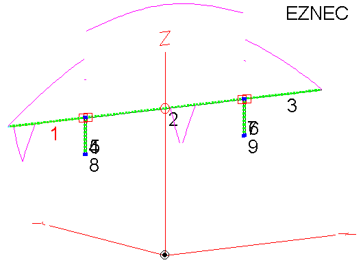
shortened antenna systems. Below is the
result of plotting current in the G5RV antenna using inductors
in the form of loading stubs as done by W5DXP in Eznec. It can
be seen that the current entering the stub is greater than current
exiting the stub. When simple inductance in Eznec is inserted
in place of the stubs, the current erroneously is shown as the
same at the both ends of the inductor. |
||
|
|
|||
|
|
|
||
|
|
|
||
|
Here
are some comments relating to the subject of current distribution
through loading coils as rehashed on rec.radio.amateur.antennas
news group: Posting by Cecil, W5DXP shedding some light on the
"theoretical" (Kirchoff and Ohm laws) arguments and
their propriety to the case: Assume a transmission
line with an SWR of 10:1. Put a series inductor in series with
the transmission line. Assuming negligible losses, the forward
current is the same at each end of the coil and the reflected
|
|
||
|
|
|
||
|
|
Page 58 |
||
 |
 |
 |
 |
Just for Fun:

Powered byIP2Location.com
Thanks for your time!
Last Updated:
February 27, 2020 21:46