

|
|
 |
 |
 |
|
|
Antentop is FREE e-magazine devoted to Antennas and Amateur Radio an
Special page devoted to
Current Distribution in the A.L.C.

Custom Search
|
ANTENTOP-
03- 2003, # 004 |
Current
Distribution in the A.L.C.
|
||
|
|
|||
|
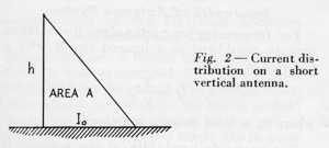
The
base coil is omitted, which "simplifies" or distorts
the picture of real current distribution in shortened radiator
with base loading coil. As we will see later, if the coil was
shown, 1 A current applied at the bottom, and current measured
at the top of the coil, authors would have seen the drop across
the coil and current at the bottom of the radiator (top of coil)
would not be 1 A, but more like shown by the shaded area in Fig.
3.
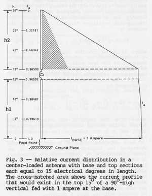
Then
we see in Fig. 3 coil inserted
in the middle of 30 deg. radiator. Coil
has "zero" physical length and current distribution
across the coil is shown as constant and as W8JI claims. The implication
is that coil magically widens the area under the current curve
over the top 15 deg. Here is the cross-hatched area that is missing
in the ARRL Antenna Book, which is really what is happening in
the coil loaded radiator. This figure implies that current across
the coil is constant and actually makes short radiator work better
than the "naked" one, without the coil (proportional
to the areas under the current curves). In reality, the picture
should show current across the coil coming from the bottom right
corner of the shaded area to the top current curve at 15 deg.
or bottom of the coil. Bruce,
W6TWW, states: "Therefore,
the current exiting the top of the coil is the same as that entering
the bottom of the coil. (This is true for conventional coils.
However, radiation from long skinny coils allows coil current
to decrease, as in helically wound antennas.) This is easily verified
by installing RF ammeters immediately above and below the loading
coil in a test antenna. Thus, the coil forces a much higher current
into the top section than would |
flow
in the equivalent part of a full 90-degree-high-antenna." So
here is qualifier that in long skinny coils, as in helically wound
antennas, radiation allows coil current to decrease. The problem
seems to be that in one case the current decreases across the
coil (helical), but in "regular" loading coil that is
not allowed, which is false. (Where was the measurement, verification?) Is
this really true or is it based on a previous reference? Lets
follow the trail to the referenced article (by W6TWW) in 1953
QST, p. 30 by J. Belrose, VE3BLW (now VE2CV) "Short Antennas
for Mobile Operation" and we see the origin of the "constant"
current across the coil and the "linearized" current
distribution..
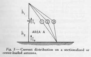
Curves
with 1, 2, 3 show various current distributions from 1 for no coil,
to 3 for coil that brings the antenna to resonance. Jack in his
calculations assumes that the current across the coil is constant
and that seems to perpetuate all the way to the latest edition
of ARRL Antenna Book. So much for the "theory". What
is the reality? I repeatedly asked W8JI to measure the current
in typical mobile coil loaded antenna, like in Hustler 80 m resonator.
His reply was that he measured thousands of coils and he found
constant current. He would not reply to this one case that represents
a typical situation and is the subject of this dispute. |
||
|
|
|
||
|
|
Page 54 |
||
 |
 |
 |
 |
Just for Fun:

Powered byIP2Location.com
Thanks for your time!
Last Updated:
February 27, 2020 21:39