|
|
 |
 |
 |
|
|
Antentop is FREE e-magazine devoted to Antennas and Amateur Radio an
Special page devoted to
Multirange Vertical Antennas

Custom Search
|
ANTENTOP-
03- 2003, # 004
|
Multirange Vertical Antennas
|
|
|
|
|
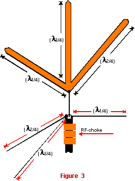
Figure 3 shows a simple design
suitable for 6 - to 17-M. Antenna has the triangular shape. Special
'sitting' should be used for the antenna design. Vibrators are
screwed in the bottom with the help of strong screws. The design
has a small mutual influence for every vibrator against each other. Figure 3 A triangular
shape antenna design
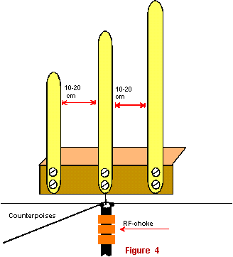
Figure 4 shows a simple
design suitable for 6 - to 30-M. Vibrators are screwed to a strong
metal angle. Figure 4 A three range
antenna on a metal angle
|
Distances between
the vibrators are 10 -30 centimeters. It is decrease the mutual
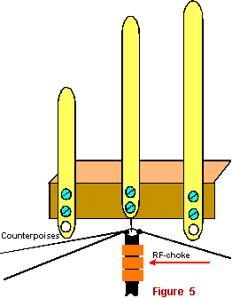
influence of the vibrators to each other. Antenna Adjusting: The antenna is adjusted by changing lengths of the
vibrators. It is not complicated. One way is to move vibrators
relatively the metal base, as it is shown in Figure 5. Do it carefully, because the vibrators
have mutual influence to each other. It needs to do additional
holes on to end of the vibrators for realization of the way. It
is possible to do one of the vibrators. This method always gives
a good result. Figure 5 A three range
antenna adjusting
Other
way is to change lengths of the upper ends of the vibrators. The
vibrators ends made from thick copper or aluminum wire. The wire
may be shortened, move in the side, as it is shown in Figure
6. But at the way an amateur must have access to ends
of the antenna. A three ranges antenna
for the low ranges Figure 7 shows a simple
design suitable for 40 - to 160-M. Vibrators made from a copper
wire in diameter 1 to 2 mm. Vibrators have length (λ/4)*1.1.
Each vibrator is matched with coaxial cable with help of its own
a 'shortening' capacitor. The shortening capacitor can have 100-pF
at ranges of 6- to 17-M, 150-pF at ranges of 20- and 30-M, 200-pF
at ranges of 40-80 meters, 250-pF at 160-M. The shortening capacitors
should be placed in a whether- proof box. Figure 8 shows another
simple design suitable for 40 - to 160-M. Vibrators made from
a copper wire in diameter 1 to 2 mm. |
|
|
|
|
|
Page 43 |
 |
 |
 |
 |
Just for Fun:

Powered byIP2Location.com
Thanks for your time!
Last Updated:
February 26, 2020 22:11