|
|
 |
 |
 |
|
|
Antentop is FREE e-magazine devoted to Antennas and Amateur Radio an
Special page devoted to
Multirange Vertical Antennas

Custom Search
|
ANTENTOP-
03- 2003, # 004 |
Multirange Vertical Antennas
|
|
|
|
|
|
|
|
|
Igor
Grigorov, RK3ZK
|
|
|
|
A
combined three-band antenna
Three band antenna fundamentals:
At a lack of the place for installation of a separate vertical
antenna for each of three upper HF ranges it is possible to use
a combined three-band antenna that works at the ranges itself.
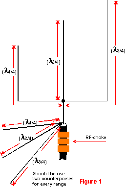
Figure 1 shows schematic of a combined three-band antenna. Figure 1 A combined
three-band antenna
The
antenna consists of from three quarter-wave verticals that are
resonated for each of working ranges. The verticals are connected
in the bottom together. Two quarter-wave counterpoises should
be use for each operation range of the antenna A coaxial cable
with 50-Ohm characteristic impedance will do well for the antenna.
A coaxial cable with 75-Ohm characteristic impedance also would
be work with the antenna, but a SWR in the coax will be higher
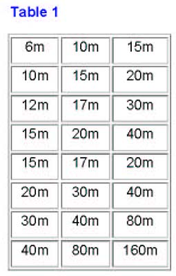
compare to 50-Ohm coaxial cable. Table
1 shows the combination of ranges where a mutual influence
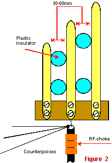
of vibrators against each other is minimum. Design of the Antenna: Three various
designs of the three- range antenna are shown below. Figure 2
shows a simple design suitable for 6 - to 15-M. The three
vibrators are placed on a small distance from |
each other. The distances
between the vibrators are fixed with the help of small plastic
insulators. The design has very strong mutual influence for every
vibrator against each other. Figure 2 Simple design
of a three ranges antenna
|
|
|
|
|
|
Page 42 |
 |
 |
 |
 |
Just for Fun:

Powered byIP2Location.com
Thanks for your time!
Last Updated:
February 26, 2020 22:08