 2 X 3 = 6
The designs make a useful contrast with each other. Both are a bit over 6' in boom length. However, one presses for higher gain and good front-to- back ratio, while the other sacrifices a bit of gain and front-to-back for a wide operating bandwidth that covers all of 6 meters (50-54 MHz) with under 2:1 SWR with a direct 50-ohm feed.
I have elsewhere shown a 20 meter model using single diameter materials with these properties, adapted from a stepped-diameter model developed by K6STI. The design covers all of 20 meters. When scaled to 6 meters, the design covers about 1.5 MHz with the desired characteristics. Here are the dimensions, using 0.5" aluminum tubing. (single-diameter elements are quite practical from 6-meters on up.)
Element        Length (ft)    Spacing from Driven Total Boom
                                Element (ft)       Length (ft)
Reflector        9.53              3.15
Driven Element   9.08              ----
Director         8.536             3.345            6.495
The performance characteristics are summarized in the following table:
Frequency      Gain      F-B Ratio      Feed Z         SWR (ref. =
  MHz           dBi        dB           R+/-jX           25 ohms)
50.0           7.92      16.55          26.9 - j20.2    2.14
50.5           8.07      22.59          26.4 - j11.6    1.57
51.0           8.24      25.86          24.9 - j 2.4    1.10
51.5           8.43      19.33          22.8 + j 7.8    1.40
52.0           8.64      14.66          20.3 + j19.2    2.34
Notice that the 2:1 SWR for this antenna, with a 51 MHz target design frequency, is well over 1 MHz, but assumes the use of a 2:1 feedpoint matching system. This can be a beta match, which will require shortening the driven element until it shows abut 25 ohms capacitive reactance, or a Tee match, which will require a bit of driven element lengthening to show inductive reactance.
The target center frequency can be adjusted up or down within 6 meters by adjusting all three element lengths by the percent of frequency change without concern for changes in element spacing of diameter. Likewise, for those more concerned with gain than front-to-back ratio, the performance at 52 MHz or a bit above that can be scaled to the target frequency, with the driven element adjusted for either resonance or a desired matching system. Changing the driven element length to create changes in its reactance by as much as 25-30 ohms has very little affect on the other performance figures.
From the same 0.5" diameter aluminum tubing, it is possible to build a 3- element Yagi with about 7 dBi free space gain and up to 21 dB front-to-back ratio. Such an antenna will show a 2:1 SWR bandwidth of over 4 MHz on 6 meters and have a direct 50-ohm feed as well. The design below is adapted from an old W6SAI design for 10 meters. The dimensions are these:
Element        Length (ft)    Spacing from Driven Total Boom
                                Element (ft)       Length (ft)
Reflector        9.734             3.391
Driven Element   9.008             ----
Director         8.01              2.73             6.121
The performance characteristics are summarized in the following table:
Frequency      Gain      F-B Ratio      Feed Z         SWR (ref. =
  MHz           dBi        dB           R+/-jX           25 ohms)
50             7.00      14.90          48.4 - j21.2    1.54
51             6.92      18.08          51.9 - j 9.9    1.22
52             6.96      20.31          51.9 + j 1.7    1.05
53             7.13      21.02          48.8 + j15.0    1.35
54             7.44      18.40          43.0 + j31.1    1.96
Notice that the gain curve is not the anticipated steady rise across the band, but shows a minor peak just below the band edge, with an insignificant dip and then a return to the normal 3-element rise. The front-to-back ratio does not peak on the target design frequency (52 MHz, for the wide-band model), but above that frequency. The SWR remains below 2:1 for a direct 50-ohm feed from below 49.5 MHz to just above 54 MHz.
The wide-band model is suited to wide-band interests, perhaps in a mechanical design that permits the user to flip it from horizontal to vertical polarization (where it, like every other Yagi, will show a broader beamwidth and up to 3 dB less gain over real ground). This would permit use with repeaters while allowing the operator to take advantage of SSB and CW openings.

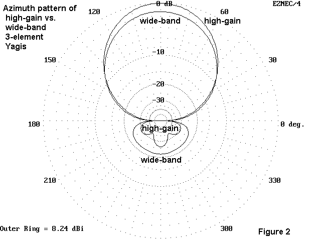
Figure 1 shows in rough scale the difference between the dimensions of the two antennas. Figure 2 contrasts the free space azimuth patterns.

Either beam is easily constructed from hardware store tubing and other
supplies. Both will be very light and easily installed at moderate
heights. You can take your pick--or you can use these notes as clues to
the design considerations for adapting them to other bands, higher or
lower.
Updated 7-25-97. © L. B. Cebik, W4RNL. Data may be used for
personal purposes, but may not be reproduced for publication in print or
any other medium without permission of the author.