 Notes on a Wide-Band 50/75-Ohm Coax Feed System for Low HF Band Dipoles and Vees

The result is a well-establish broadening of the operating SWR-bandwidth. These notes are a bit of follow-up that seemed interesting as the numbers emerged from some modeling exercises. I used a dipole resonant at 3.75 MHz, ignoring the geometric mean part of the scheme, since I had no two special frequencies in mind. Actually, the scheme provides a certain wide- banding effect about whatever center frequency is chosen, and the available bandwidth is independent of any desired pair frequencies.
This system is only one of many techniques used to broadband 80 meter antennas. See Chapter 9 of the current ARRL Antenna Book for a compendium of techniques.
As with all matching systems, the SWR at the antenna relative to 50 ohms does not change in this broad-banding scheme. However, line losses at the lower HF bands are not--for many purposes--sufficiently large to make a case against this or other wide-banding techniques with coaxial feed lines. The factors that produce wide-band operation (using the conventional <2:1 SWR measure for convenience) include the impedance transformation along the transmission line at frequencies above and below the dipole resonant length and the physical lengths of coax cut for that resonant frequency.
The easiest way to get a good grasp on how the wide-band matching system works is to look at the following table of figures. Remember that the antenna is self resonant at 3.75 MHz. At 3.65 MHz, the antenna is short and the feedpoint impedance is capacitively reactive. At 3.85 MHz, the antenna is long and the feedpoint impedance is inductively reactive.
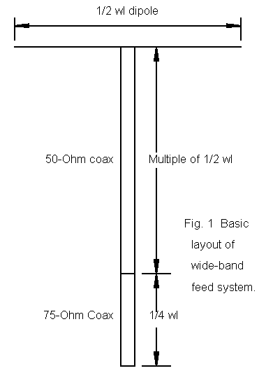
The 50-ohm coax run (using a cable with a VF of 0.765) is 1 wl long at the same 3.75 MHz frequency. A full wl returns exactly the same impedance as at the antenna terminals. However, at 3.65 MHz, the coax run is short of the 1 wl mark. The continuous impedance transformation has not completed a full cycle. The value it returns at its length (0.97 wl) is higher resistively than the antenna feedpoint impedance at this frequency and less capacitively reactive. At 3.85 MHz, the coax run is longer than 1 wl (1.03 wl) and has begun a new cycle of transformation. It reaches a resistive value higher than the feedpoint value, but is less inductively reactive. These are the values going into the so-called 75-ohm matching section.
Frequency                     3.65 MHz       3.75 MHz       3.85 MHz
Dipole Feed Impedance          85.2 - j45.9   91.6 - j0.5    98.1 + j44.5
50-ohm SWR                         2.36           1.83           2.47
50-ohm Coax (200.6')          < 1 wl         exactly 1 wl   > 1 wl
Impedance at coax end         110.1 - j26.7   91.6 - j0.5   121.3 + j15.1
75-ohm Match (44.3')          < 1/4 wl       exactly 1/4 wl > 1/4 wl
Impedance at match end         47.7 + j 9.8   61.4 _ j0.3    45.4 - j 3.7
50-ohm SWR                         1.23           1.23           1.13
0.25 wl matching sections transform resistive impedances according to the following simple formula:
where Zo is the characteristic impedance of the matching section transmission line, Zin is the impedance on the antenna side of the section and Zout is the impedance on the station side of the section. The length of the matching section is precise for 3.75 MHz and for the 0.66 VF 75-ohm cable used. The reactance at 3.75 MHz is too small to make a difference, so we can plug 75 ohms and 91.6 ohms into the second version of the equation and get a Zout of 61.4, just what our model shows.
At 3.65, the matching section is shorter than 1/4 wl. Moreover, we have significant reactance going into the section. However, even if we ignore these deviations, we get a simplified impedance for Zout of 51.1 ohms, only 3.4 ohms off the model. Likewise, the section is longer than 1/4 wl at 3.85 MHz, and Zin has reactance. Still, the simplified equation predicts a Zout of 46.4 ohms, only 1 ohm off the modeled mark.
These convenient transformations of impedance do not go on indefinitely on either side of resonance. The band edges of 80-75 are a little over 6.5% removed from the center frequency, and already the combination of impedance transformations in both the 50-ohm and the 75-ohm sections yield impedances at the matching section end that produce high SWRs.
One other quick note for the adventuresome: it is not necessary to use resonant antennas and exact multiples of 0.5 wl for the 50-ohm coax run. within limits, one can tailor together specific antenna feedpoint impedance characteristics and transmission line length yielding specific impedance transformations to produce desired impedances entering the matching section (or eliminating it). These cases tend to fall into the realm of the special rather than into the collection of generally applicable techniques for ham antennas.
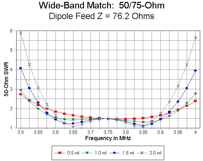
My dipole at 120' over level medium ground had an independent feedpoint Z of 76 ohms. I am reading from graphs at this point, but hope to make the data more precise later.
50-ohm Length  Lower limit    Upper limit    Bandwidth      Lowest SWR
     0.5wl          3.57           3.96        0.39              1.45
     1.0            3.55           3.96        0.41              1.30
     1.5            3.57           3.93        0.36              1.10
     2.0            3.58           3.91        0.33              1.07
Figure 2 provides a graph of this family of curves.

The table has several interesting features. First, for a 0.5 wl 50-ohm run, there is only one SWR minimum, roughly at the self-resonant frequency of the dipole. With an independent feedpoint impedance of 76 ohms, the SWR shows a shallow curve.
Second, for lengths of 50-ohm coax of 1 wl and up, the double minima curve emerges. With the given independent dipole feedpoint impedance, bandwidth is greatest with a 1 wl run and diminishes above that. In fact, as the length of 50-ohm coax is increased, the rise in SWR is steeper at both the low and high ends of the band. However, the minimum SWR become lower with increases in 50-ohm line length. The SWR at the dipole's self-resonant frequency remains unchanged throughout, since at this frequency, each 50- ohm coax run provides the same impedance at the beginning of the 75-ohm matching section.
I reran the exercise, each time lowering the dipole height by 10' in order to see what effect an increasing independent feedpoint impedance might have on the curves. I adjusted the independent dipole length as necessary for resonance and imported that length to the model with transmission lines. First the numbers:
110' up"  Z=83 ohms
50-ohm Length  Lower limit    Upper limit    Bandwidth      Lowest SWR
     0.5wl          3.55           3.97        0.42              1.35
     1.0            3.54           3.96        0.42              1.25
     1.5            3.56           3.93        0.37              1.10
     2.0            3.58           3.91        0.33              1.05

100' up"  Z=89 ohms
50-ohm Length  Lower limit    Upper limit    Bandwidth      Lowest SWR
     0.5wl          3.53           3.97        0.44              1.26
     1.0            3.54           3.97        0.43              1.15
     1.5            3.56           3.93        0.37              1.04
     2.0            3.58           3.90        0.32              1.09

90' up"  Z=92 ohms
50-ohm Length  Lower limit    Upper limit    Bandwidth      Lowest SWR
     0.5wl          3.53           3.99        0.46              1.25
     1.0            3.54           3.96        0.42              1.10
     1.5            3.56           3.93        0.37              1.01
     2.0            3.58           3.90        0.32              1.05
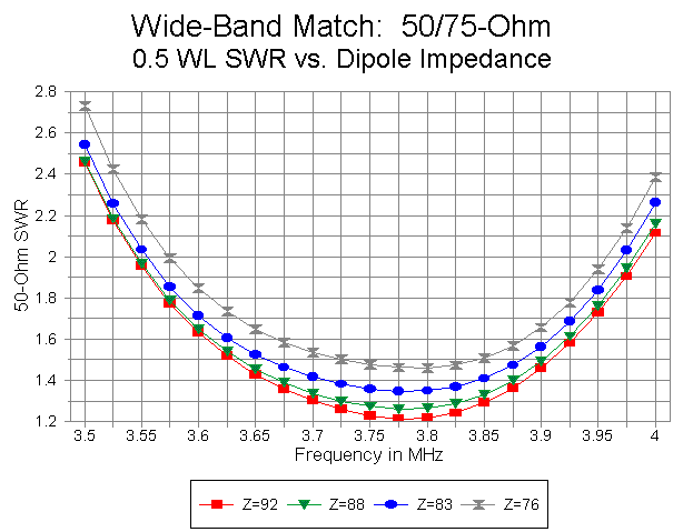
As the independent feedpoint impedance of the dipole increases (within the boundaries of the test runs), the performance of the 0.5 wl 50-ohm coax run improves. The curves over all the tests for this length of line are largely congruent, and the improved performance with increasing feedpoint impedance occurs because the impedance presented to the 0.25 wl 75-ohm matching section grows closer to the value needed for a 50-ohm impedance at the transmitter end. Figure 3 illustrates the trend.

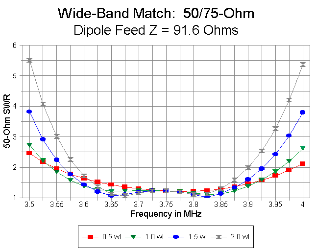
Although not especially extreme, the slope of the SWR curves for the two longest runs of 50-ohm line grow steeper with increasing independent dipole feedpoint impedance. Figure 4 illustrates the curves for 2 wl 50-ohm runs at 4 dipole feedpoint impedances. Band edge values are about 5.5:1 for 2 wl runs and 4:1 for 1.5 wl runs.

By contrast, with a 1.0 wl run, the band-edge SWRs are close to 3:1, while with a 0.5 wl run, the band-edge values are about 2.7:1 for the worst case and 2.5:1 for the best case (at the lower end, with lower values at the upper end of the band). The differentials in bandwidth are especially apparent when comparing 50-ohm coax run lengths at higher independent dipole feedpoint impedances, as illustrated in Figure 5.

The system feedpoint impedance values do not account for dissipative line losses. These losses ordinarily show up at the shack end of the line as slightly lower SWR readings. A program such as Dean Straw's TLA can be a great aid in finalizing SWR expectations and estimating losses for each particular installation.
However, if one is seeking the maximum possible coverage of 80-75, then one might consider restricting the length of initial 50-ohm coax run to 0.5 wl or at most 1.0 wl. One can insert the 75-ohm matching section at this point and use 50-ohm coax the rest of the way to the shack, as show in Figure 2. Since the impedance values fluctuate across the band by as much above 50 ohms as below it, some further impedance transformation will occur, but it will be in virtually all cases less radical at the band edges than would be the case of using the longer initial 50-ohm runs indicated in the charts.

The numbers and suggestions are limited, of course, by the limitations of
the models and modeling program. They may require field adjustment in
accord with the circumstances of any given installation. However, I hope
they are useful to those thinking about using the feed system Dave Leeson
and Frank Witt have brought to our attention.
Updated 11-29-97. © L. B. Cebik, W4RNL. Data may be used for
personal purposes, but may not be reproduced for publication in print or
any other medium without permission of the author.