 Notes on All-Band Use of Vertical-Plane
Deltas
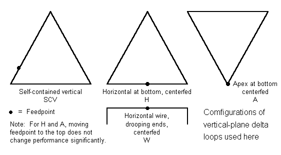
First, the antenna. A vertical-plane equilateral delta for 40 meters will be about 48.5' wide and 42' high. This places limits on the height above ground of the lowest point, since with a 35' low-point height, the high point is 77' up. For the examples below, a standardized 15' bottom point is used, with a 57' upper point. See the following sketch for the various configurations of the vertical-plane delta, along with a small, simple antenna with which we might compare it.

b. As the antenna is raised by another 5-10 feet, the secondary lobe increases, so that with a bottom height of 40', the antenna's secondary high angle lobe at 60 degrees is down by only 4 dB or so. As the antenna is lowered, gain decreases very slowly (imperceptably?), and the elevation angle of maximum radiation increases very slowly (about 1 degree for each 5' of lowering). A 15' lower wire or point height provides good performance within this class of antennas.
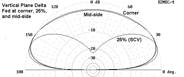
As the following pattern shows, the azimuth pattern of a vertical plane delta fed as an SCV is a broad oval.

c. Moving the feedpoint to a mid-side location increases gain by increasing the amount of horizontally polarized radiation produced by the antenna. This increases the elevation angle of maximum radiation as well as spreading the main lobe vertically to permit considerable amounts of higher angle radiation. In affect, moving too far from the feedpoint prescribed for use of the vertical plane delta as a vertical antenna tends to defeat that purpose. However, the vertical-use feedpoint itself is not critical within say 5% or so of the recommended point.
d. Moving the feedpoint to a corner also increases the amount of horizontally polarized radiation. The result is similar to using a midpoint feed. The elevation angle of maximum radiation only increases slightly (approximately 5 degrees), while the gain remains about the same. The elevation pattern becomes a flatted oval showing significant higher angle radiation only a very few dB down from the maximum. The result is the same as for the mid-side feedpoint: a relative defeat of the use of the antenna as a low-angle, low-gain, high signal-to-noise ratio antenna.
Every version of the self-contained vertical requires feeding about 1/4 wavelength from a peak position in order to maximize vertically polarized radiation. Selection of some other feedpoint will show an increased proportion of horizontally polarized radiation, with a consequential increase in sensitivity to higher angle radiation and an increase in QRM and QRN levels relative to the strength of low angle DX signals.
1. The vertical plane delta fed for maximum vertically polarized radiation 1/4 wl away from the apex on one side.
Freq      Gain      TO angle    Az Angle       Feed Z     Pattern
notes
7.15      1.3       19            90          145-j  20     oval
10.1      2.0       16            90         2700+j2600     oval
14.15     5.6       59            90          310+j 100     oval
18.1      5.2       34            64         1300-j1300     off-center peanut
21.1      5.1       36            52          480+j 190     off-center peanut
24.95     5.5       49            99         1200-j1300     boomerang
28.1      6.3       38            90          360+j 190     bulgy square
Although the 30-meter performance is low angle, the gain is low. Otherwise, the elevation angle of maximum radiation is quite high. See the last antenna in this series.
2. V-delta, horizontal down, fed at center of the horizontal
Freq      Gain      TO angle    AZ angle      Feed Z        Pattern
notes
7.15      4.7       56            90         115+j  30     oval
10.1      5.8       33            90        1400+j3900     peanut
14.15     5.9       60            90         360+j  27     oval
18.1      8.3       40            90        1300-j1300     long peanut
21.1      6.4       40            90         185+j 170     oval
24.95     8.8       47            90        1300-j 750     long, thin oval
28.1      5.5       40            25         330+j 300     bulgy
rectangle
3. V-delta, horizontal up, fed at bottom apex
Freq      Gain      TO angle    AZ angle      Feed Z      Pattern notes
7.15      6.0       37            90         140-j  10     oval
10.1      7.2       27            90        2700+j1400     oval
14.15     6.6       71            90         250+j 160     oval
18.1      6.3       44            90        1000-j1900     oval
21.1      5.6       69            90         110+j 180     oval
24.95     7.4       33            90        1500-j1700     bulgy oval
28.1      8.6       53            90         280+j 230     bulgy oval
For these two variations, the radiation angle is quite high. Lower lobes exist, but at lesser strength than the high lobes, except as noted for a few exceptional cases in the tables.
Changing the feedpoint from bottom to top does not significantly change the patterns of the center-fed horizontally polarized antennas.
4. V-delta, horizontal down, fed at lower corner
Freq      Gain      TO angle    AZ angle      Feed Z      Pattern notes
7.15      1.2       27            90         145+j  10     oval
10.1      1.2       18            90        3500+j1900     oval
14.15     4.4       43            32         260+j 180     2 lobe, edgewise
18.1      5.0       39             0         590-j1600     2 lobe, edgewise
21.1      5.0       36             0         130+j 220     2 lobe, edgewise
24.95     5.4       25            40        1000-j1400     2 lobe, edgewise
28.1      6.6       23            36         300+j 280     2 lobe, edgewise
Above 30 meters, the pattern of the lower-corner-fed delta becomes two large lobes off the edges of the delta, with nulls off the delta faces that vary with the band. The lobe in the direction away from the feed point tends to be flatter with signs of becoming a double lobe, and on some bands the azimuth angle of maximum radiation is offset from the delta edge. (The elevation patterns for this feed configuration do not appear in the collection of patterns shown below.)
5. 48.5' horizontal dipole with 9.1' drooping ends: Let's compare the performance of this simple antenna placed at a height of 57' up. This is the same as the top height of the deltas modeled here. It is center-fed.
Freq      Gain      TO angle    AZ angle      Feed Z     Pattern notes
7.15      6.5       33            90          69-j   2     oval
10.1      8.1       24            90         210+j 800     oval
14.15     7.8       17            90        5500-j1100     oval
18.1      9.4       13            90         120-j 900     oval
21.1      7.7       11            42          55-j 130     4 lobes
24.95     7.7       10            55         280+j 790     4 lobes
28.1      7.6        9            65        3050+j1700     4 lobes
The 4-lobe patterns have indistinct lobes and hence might have been classified as bulgy rectangles or squares.
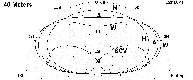
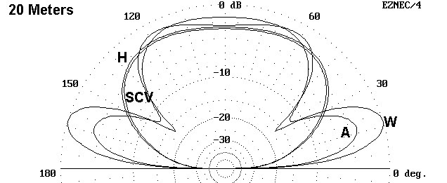
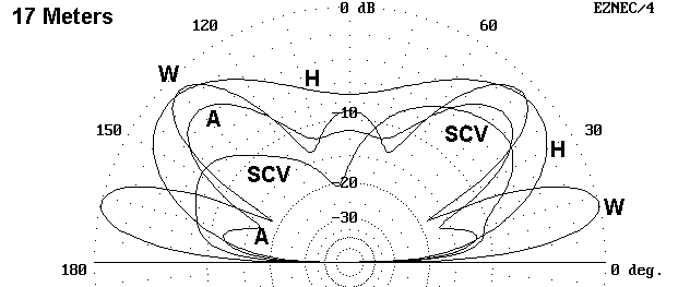
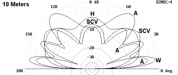
This simple antenna that takes 1/2 the wire of a delta and spreads no farther than the horizontal wire of the delta has a lower elevation angle of maximum radiation and in all but a couple of cases, higher gain than any of the multiband deltas, when the deltas are set up in the vertical plane. 20 and 10 meters may present matching problems for limited range tuners. To get a sense of the pattern differences involved, the following elevation patterns may be helpful. Each antenna is shown for each band. Elevation patterns are taken at the azimuth angles yielding the highest gain for each model. (The corner-fed models are omitted, since the graphics are already verging on being "cluttered.") The general trend for the simple wire antenna to provide more gain at lower elevation angles is clearly apparent.



A full-length 40-meter dipole fed with paralel transmission line via and ATU would show slightly better performance. Open wire feeders are recommended for any multi-band wire antenna where the feedpoint impedance varies widely.
Again, these numbers apply only to deltas set up in the vertical plane. Deltas and other loops set up in the horizontal plane are another story entirely.
The figures and patterns speak for themselves, so no recommendations are
needed. However, what was said earlier bears repeating. The delta loop
when set up vertically, can be used on all bands, just as can almost any
wire antenna that is at least 3/8 wavelength long at the lowest frequency
to be used. However, whatever the configuration (apex up or down) and
whatever the feedpoint (corner, apex, mid-horizontal, SCV, mid-side), it is
unlikely to outperform even a simple center fed wire at the same height as
the top of the delta.
Updated 10-13-97. © L. B. Cebik, W4RNL. Data may be used for
personal purposes, but may not be reproduced for publication in print or
any other medium without permission of the author.