

If there are problems, they number two: 1. The antennas have low gain, and 2. We need either a braced vertical or something high from which to hang the long wires. I can help a bit with the first problem, but the second is yours. If you have some tall trees, you might consider hanging support ropes as high as you can go and suspending your vertical dipoles from them. Tall towers for upper HF beams can also serve as anchors for a vertical array.
However, let's keep the gain requirements modest--say about 3 dB more gain than from a single vertical dipole. But let's also keep active our aim of working the world. Assuming that we can hang 3 wires, we can make a nice little triangular parasitic array that will do just the job we need.
If we can manage the height, we can build a switchable directive parasitical array from 3 wires. Figure 1 shows the general layout. Essentially, the system consists of three verticals laid out so that two form parasitical reflectors for the third, which is a driven element. The parasitical arrangement is capable of about 3 dB gain over a single vertical and yields between 15 and 16 dB front-to-back ratio without any effort expended on calculating and pruning a phasing system. If these benefits are sufficient, then we can proceed.

The right side of Figure 1 shows the way to calculate the positions of the three elements in an equilateral triangle. If we know the face length, A, then the others will fall in place this way:
B = .577 A
C = .289 A
D = .5 A
How large shall we make A? Actually, the length of A depends on two factors, neither of which is some special fraction of a wavelength taken from theory. Letting the distances between verticals run from 0.12 wl to about 0.25 wl yields nearly the same gain with about the same front-to-back capability (using parasitical arrangements). So what might set our distance?
First, the driven element will have to be shortened from its natural resonant length when isolated as a dipole. We shall shorten all three legs accordingly, since each will serve in its turn as the driven element. However, reducing the length of all the wires will require us to load the two legs to make them act as reflectors. We can do this the hard way with loading coils, or we can do it the easy way with shorted coax stubs. We shall bring the stubs to a central junction box, where the reflector stubs will be shorted and the driver stub becomes just another short length of the feed system. In this way, we can use a remote switch and some relays to change the direction of the array. So, the length of the feedline used as a shorting stub helps to determine the length B, since we may wish to bring the line directly to an elevated box centered among the 3 wires.
Second, the face length A determines the feedpoint impedance of the driven element. When the face length A is about 0.16 wl, the source impedance of the driver approaches 50 Ohms, a very handy value indeed. At 7.1 MHz, this distance is about 22 feet. With this face length, the distance B becomes about 12.7 feet. Will the loading stubs be at least this length for the assembly? Actually, we get a little length to spare. The required stub for 50-Ohm, 0.66 velocity factor line will be 16.4' long, enough to allow some play in the line for a direct connection.
For those unfamiliar with calculating the length of shorted stubs, the basic equation for determining the inductive reactance from the length of transmission line is

where L is the line length and WL is a wavelength, both in the same units, VF is the velocity factor of the line, ZO is the line's characteristic impedance, and XL is the inductive reactance. Solving for L, the line length, we get
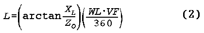
where the terms have the same meaning as in equation 1. If we want to place the junction box on the ground, we can add a half wavelength of line (taking the velocity factor into account) and achieve the same reflector loading goal.
Here are some starter dimensions for both 40 and 30 meters, assuming that each antenna starts 10' off the ground.
Triangle factors (measured in feet):

Frequency      A         B         C         D
7 .1           22'       12.7'     6.35'     11'
10.1           15.5'      8.95'    4.47'      7.75'

Antenna wire (#12) and cable factors (measured in feet):

Frequency      Vertical Length     Top height     Stub length (RG-213)
 7.1                65.9'             75.9'          16.4'
10.1                46.325'           56.325'        11.7'
If you move up or down from the given vertical positioning, expect some small changes in the required dimensions, but none so great that you cannot make the system work.
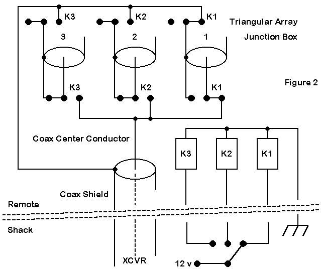
Figure 2 shows a simple switching system for the array involving three DPDT relays. The schematic shows antenna 1 as the driver, with verticals 2 and 3 having shorted stubs. Note that the stub shields or braids are isolated from the main feedline braid when the stubs is shorted. When a stub becomes an extension of the feedline, its braid is connected to the feedline.
The relays can be anything from small items purchased locally for low power use to beefy units for high power operation. The components require a waterproof box, but the coax connectors should not be directly grounded to the case, since that would defeat braid isolation. In addition to the usual coax feeder to the shack, a 4-wire rotator cable (or a similar cable suitable for outdoor use) carries power to energize the relays, according to the switch position in the shack. Of course, at the shack end of the line, you can make up any desired indicator system, from a simple row of LEDs to a small map with the lamps showing the part of the world at which the array is aimed.
In the schematic, when no power is applied (that is, when the station is idle), all relays revert to the shorted stub mode, and the feedline is disconnected from the three vertical wire dipoless. You may add whatever other safety features you deem appropriate to the junction box system.

Figure 3 shows an overlay of the three possible azimuth plots, one for each switch position. However, do not take these plots completely at face value.
First, note that there are slight nulls in the coverage. Although they are shallow, you may wish to orient the array so that the nulls point at places where no ham lives.
Second, the gain figure holds only for placement of the antenna over average ground. As the soil gets either better or worse in the general category scheme, the gain will rise. (The actual pattern of gain vs. height above various soils grows more complex as we take into account more varieties of coil conditions.) However, the improvement over a single vertical wire will remain about constant. Although "average soil" yields nearly the lowest gain figures of any soil (depending upon the exact vertical height over it), the take-off angle will decrease as the soil improves and will rise as the soil condition grows worse, almost wholly independent of the gain.
Third, the figures show the slightly higher gain figures yielded by the 30- meter version of the array. 40-meter gain figures are about 0.15 dB lower due to the lower effective height of the antenna, since we placed each at a minimum height of 10 feet.

The elevation plot shown in Figure 4 shows the vertical array benefits to their best advantage. The low take-off angle favors DX skip angles, while the front-to-back ratio is very useful, if somewhat short of astounding.
The absence of significant high angle lobes, including the total absence of one directly overhead, is also beneficial for communications, since QRM and QRN originating at short skip distances are naturally attenuated, relative to a horizontal dipole or similar antenna. (However, this feature does not affect local area noises, many of which are vertically polarized.)

The SWR curves for the arrays are good (but not perfect) for 40. Sliding the design center frequency a bit higher or lower than 7.1 MHz will allow coverage of a desired band edge. As you move lower than the design center frequency, the pattern loses some front-to-back ratio, but adds a bit of gain. Higher up, the gain drops, but the front-to-back ratio is sustained.
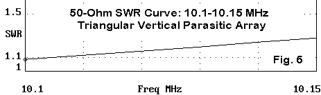
Within the narrow confines of 30 meters, SWR is no problem at all. The band is not wide enough for the pattern to change significantly.
ON4UN, in his justly famous Antennas and Techniques for Low Band DXing, devotes an entire chapter (11) to phase-fed vertical arrays. However, vertical Yagis, that is, parasitical arrays, receive scarcely 1 column of attention (in Chapter 13). Granted, a correctly phase-fed vertical array is capable of a very deep 180-degree null. However, the overall front-to-rear ratio may not for many operators be sufficiently superior to that of a parasitical array to justify the effort of perfect phasing. In addition, the perfect null does not occur at the same phasing among elements as maximum gain, and the gain difference may approach a full dB.
Those who prize the silent rear will continue to phase-feed their systems carefully. However, those who prefer simplicity in their installations may wish to explore parasitic techniques to achieve a compromise between gain and front-to-back ratio. Ted Hart, W5QJR, showed a 5-wire design a few months back in these pages. You might consider this 3-wire array the little brother of his system, since it is essentially a 2-element vertical Yagi with a double reflector. Like the bigger system, with proper switching, it will cover the entire horizon with a bit of gain and some useful front-to-back ratio.
Of course, for many, the required height to implement this system may be out of reach. Many of us use verticals that are considerably shorter than a full 1/2 wl long. As I shall try to show in a later item, all is not lost: there are triangular possibilities for the short vertical operator.
Updated 2-5-99. © L. B. Cebik, W4RNL. This item first appeared in AntenneX, Nov., 1998. Data may be used for personal purposes, but may not be reproduced for publication in print or any other medium without permission of the author.