 The 40-Meter 3-Way Special
The array consists of a triangle of three off-center-fed vertical dipoles close to the ground and no more than 22' above ground at their peaks. Each vertical dipole is end loaded with an element extension device--hats and near-hats. Each element has an inductive reactance at its off-center break. The driven element inductor acts as a beta-match shunt inductance, while the reflector inductor acts as a loading element to electrically lengthen the element. Quarter-wavelength coax lines to each vertical act as a power carrier for the driven element and as an open circuit for the reflectors through a remotely switched bank of three relays centered in the triangle of verticals. No ground plane is needed.
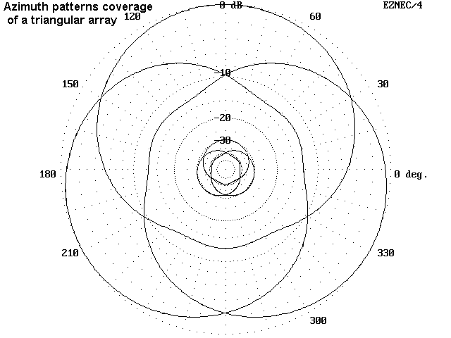
The result is an array with modest gain (which varies with the method of element end loading), better than 10 dB front-to-back ratio, a low elevation angle of maximum radiation (about 24 degrees, with a wide vertical lobe for lower angle signals), and little high angle radiation. Switching provides complete 360-degree coverage at nearly full gain, divided into three quadrants.
Let's divide the concepts underlying this array into easy-to-digest chunks.
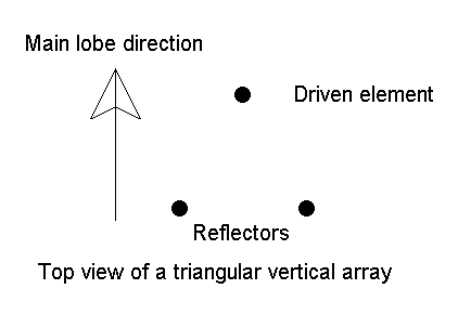
We can add a modicum of gain and extra front-to-rear nulling by using three verticals, arranged in an equilateral triangle, 1/4 wl per side. The reflector verticals are tuned in the same way as a single reflector. The sketch shows the basic layout and direction of the main lobe.

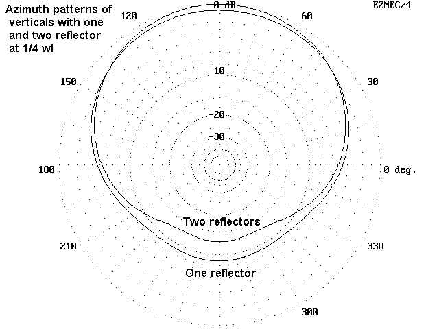
The following azimuth patterns compare the performance of 1- and 2- reflector arrays. Note that these patterns might be individually improved by careful tweaking of values, while the rearward nulls might be deepened by the use of a phasing line system. For a simplified, non-phasing-line system, the 1/4 wl per side triangle is important to further steps in the final array developed here.


This array has been used, although with 1/4 wl monopoles, it requires extensive ground planing. Typically, the means used to convert driven elements into reflectors and back tend to be complex. Most examples have used phasing netowrks to produce the deepest possible nulls to the rear. See for example, the section (4.11) in ON4UN's Low Band DXing (pages 11-48 to 11-54) for techniques used to phase feed triangular arrays from 0.145 to 0.29 wl per side.
If 10-12 dB front-to-rear performance for a 3-way array is sufficient, we may omit the phasing line and use the phasing that results from the parasitical arrangement of elements. However, vertical monopoles with groundplanes (not to mention full size vertical dipoles) are very tall on 40 meters. So let's rethink the antenna elements.
As described in other notes in this series concerning the top-end loading of half-size 80-meter verticals, a hat does not have to be perfectly symmetrical to yield insignificant horizontal radiation. For most purposes, a horizontal pattern that is down by 30 dB from the total far field pattern has an insignificant effect on antenna performance. However, such non-symmetrical element extensions usually reduces the operating bandwidth and gain by a small (but not insignificant) amount.
Here is a small sample of possible hat arrangements.

For a 1/4-size dipole (about 17.5'), standard capacity hat assemblies will have a radius well over 7 feet, and the simple square with a perimeter requires a spoke length of about 8.5 feet. Spirals and solenoids can be made much smaller, although they will require just about the same overall length of wire. For example, a helix of 2 full turns plus a little can be arrange with a radius of about 2 feet, for easier mechanical construction. See the notes on linear loaded half size verticals for other possible element extension ideas.
Hat size will also vary with the exact distance from the ground of the dipole bottom end. The models used here placed the lower end about 4.5' off the ground with the tops at 22' up.
Each vertical dipole will be identical. For 7 MHz, they should be resonated without any attachments at about 100 kHz higher than the desired center frequency of operation. This will produce an independent feedpoint impedance of about 27 - j40 ohms at the target frequency. This impedance is of some importance to the array's operation.
So let's feed the dipole off center, namely, at the lowest point before entering the lower hat assembly. The small distance from the element's electrical center (0.06 wl) makes about a 1-ohm difference in feedpoint resistance. The radiation pattern difference and the currents on the antenna element are virtually unaffected. (If you model the dipole using center and off-center feed, be sure to switch to a constant power option rather than using a voltage or current source. Otherwise, the current readings will not be comparable.)
With our off-center feed, the coax is now only 4.5' off the ground, a much more manageable position from a mechanical standpoint.

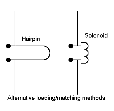
The figure illustrates the stub and coil options. A coil of about 1.15 microH is required for the inductive reactance of about 50 ohms. A coil 1" long and 1" in diameter with about 8 turns of #12 wire will satisfy this requirement. A slightly smaller coil of 1/8" diameter aluminum wire would also work well and not incur bi-metallic effects common to aluminum-copper junctions, but at a slight cost in Q due to the slightly higher resistance of aluminum.
For the reflectors, the loading inductance makes the element electrically longer--just about the right amount to act as a first-rate reflector for the driven element.
When the three verticals are arranged as an equilateral triangle about 35.1' on a side, the driven element shows an impedance of about 30 - j 25 ohms. This figure is just about ideal for using a shunt beta inductive reactance in the 50-60 ohm range. This is the function of the inductor at the feedpoint of the driven element.
A 1/4 wl length of transmission line is useful in switching. If we ground the end at the center of the array, the end at the antenna element will show a very high impedance, essentially an open circuit. The high impedance in parallel with the inductor at the element feedpoint means that the currents distributed along the element will see only the loading inductance. This condition is perfect for the element to function as a reflector.
However, if we connect the coax at the array center end to a source of RF, then the 1/4 wl section simply acts as a continuation of the 50 ohm line. The shunt beta inductor in conjunction with the series capacitive reactance at the antenna feedpoint form an L-circuit that converts the low resistive component to 50 ohms (or thereabouts).
If we place three SPDT relays in a weather-proof box, we can remotely switch which vertical receives power while the other two act as reflectors. The simplified diagram shows the scheme.

System gain for the triangular will vary from 1.5 dBi to 4.5 dBi depending on the quality of the ground in the region most affecting the far field pattern. (Gain will be even higher near salt water, but few of us live on an island.) The front-to-back ratio will usually be better then 10 dB and often exceed 12 dB (2 S-units).
The operating bandwidth is likely to be fairly narrow, so the antenna may be best suited for CW operators (who seem more comfortable with favorite operating frequencies that are fairly narrow in scope).
The models used here used vertical elements of 1.25" diameter aluminum. One might use larger diameter elements for both structural and bandwidth improvements. The physical model under development here will likely use PVC and CPVC for all nonconductive elements, including the vertical pipes that keep the elements at least 4.5' off the ground. The short verticals should be easily supported without the use of concrete if the base PVC section is capped with drainage holes and a gravel counter-weight filling below the soil level. Other construction ideas abound.
The principles of this array are adaptable to longer dipoles and even to antennas considered to be monopoles with elevated ground planes (which are- -whatever we choose to call them--still dipoles). This has been an exercise in putting fundamentals together. Hence, I claim no originality for the array--and indeed, it may well have been published many times before. It is such a natural, that I would be surprised if it has not appeared numerous times in print--even if in different rubric.
But if I have been clear enough in saying how these pieces go together,
then perhaps you are a step closer to being able to put your own favorite
pieces together to make your own ideal array.
Updated 7-20-97. © L. B. Cebik, W4RNL. Data may be used for
personal purposes, but may not be reproduced for publication in print or
any other medium without permission of the author.