 Systematic Trap Modeling
This brief report is the first step in the process. It models a 10-20 meter dipole using traps that consist of 1.2 microH inductors and 26.92 pF capacitors, resonant at 28 MHz, consistent with common trap practice. As previously noted, the traps are treated as loads on the ends of the 10 meter sections of the antennas. Modeling the traps consisted of calculating the requisite value of the equivalent parallel resistance for each trap Q level for each of the two bands and then inserting the trap as a parallel R-L-C load in the last segment of the outer ends of the 10-meter wire, with 20-meter wire extensions added. The antennas used approximate 3" segments throughout. Hence, trap length is considered for these models to be 3" per trap.
The total antenna assembly was resonated within +/-1 ohm of reactance on each band for each wire size and level of Q. Selected frequencies were 28.5 MHz and 14.175 MHz, which were considered fair samples of antenna performance with the traps selected.
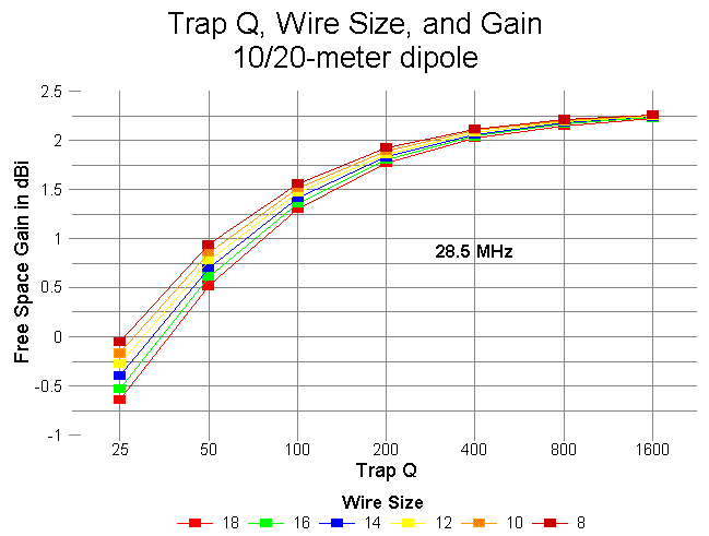
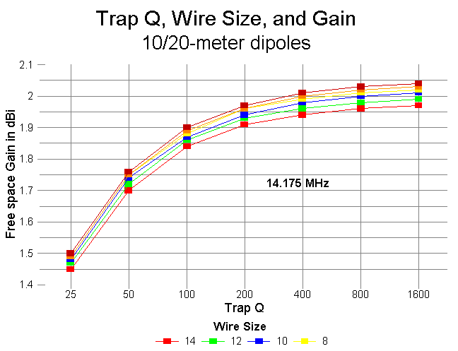
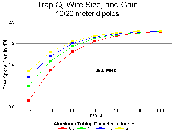
For the test, trap Qs began at 25 and were doubled up to 1600. The lowest end of the scale represents a well-worn or badly designed unit. The upper end (800 and 1600) represents what might be expected from transmission-line stub inductances. The midrange values from 100 to 400 represent a typical range of trap Q values for inductors of various types. Although inductor Q tends to vary with frequency, it was held constant for both 20 and 10 meters for this modeling exercise.
The initial exercise modeled trap dipoles constructed from copper wire of AWG sizes 18 through 8. The following table lists the wire diameters for reference.
AWG Size       Diameter in inches       AWG size       Diameter in inches
     18             0.0403                   12             0.0808
     16             0.0508                   10             0.1019
     14             0.0641                    8             0.1285
This size range carries the project up to about 1/8" in diameter. A later portion of the study will systematically chart performance for aluminum wire from 0.50" to about 2.00" in diameter.
Note that there is very little difference in performance when Qs reach 800 and above, that is, when well-designed transmission-line stub inductors are used. However, the gain levels reached with such Q levels exceed the gain of a standard full-size 10-meter wire dipole of the same material, indicating that the gains of earlier models employing transmission-line inductors as physically modeled entities are not aberrations, but consistent with modeling high-Q traps as loads. One advantage of transmission-line stub inductors (besides their inherent high Q) is the ability to design them for light weight and relative freedom from concerns about voltage breakdown or current burn-up.
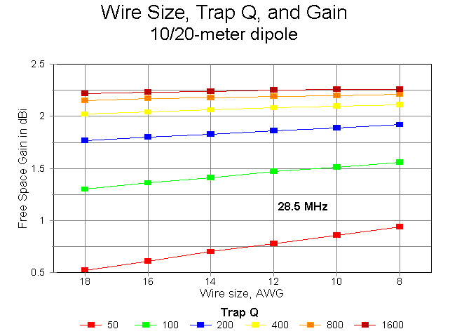
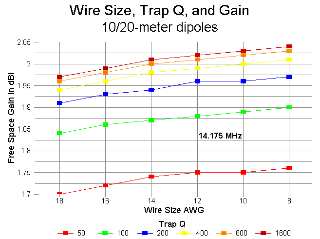
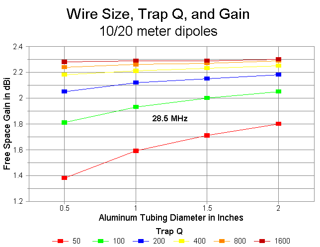
The chart showing each Q-level as a separate line across the wire-size values has the advantage of more dramatically showing the effects of trap Q on antenna gain. Little is gained using fatter copper wires than #12 or #14, but much is gained with each doubling of Q up to the Q=800 level.
The total length variation in the outer length of the antenna to achieve resonance was only 7.2" across the entire span of wire sizes and Q values modeled. Changes required for the 10-meter segment of the antenna covered a maximum range of 3" for the same spread of wires and Qs. Feedpoint impedances showed a greater range of variation and will be graphed at a later date. Throughout the exercise, the feedpoint impedance of the antenna on 10 meters exceeded 80 ohms, while on 20, the feedpoint impedance reached up to 75 ohms only for the lowest Q and smallest wire size. These values can be changed to some extent by judicious selection of trap L and C.
The feedpoint impedance on 10-meters for this collection of antennas ranges from a high of nearly 120 ohms for the lowest value of Q and the thinnest tubing to values near 80 ohms for higher Qs and fatter tubing. Although the progression of feedpoint impedances is generally inversely proportional to both Q and wire diameter, for Qs from 200 upward, the feedpoint impedance actually shows a very slight increase with the largest tube diameters. The increase is only about 1 ohm for 2" tubing, but the progression is distinct and would likely continue with even larger diameter tubing. Operationally, the increase is insignificant.
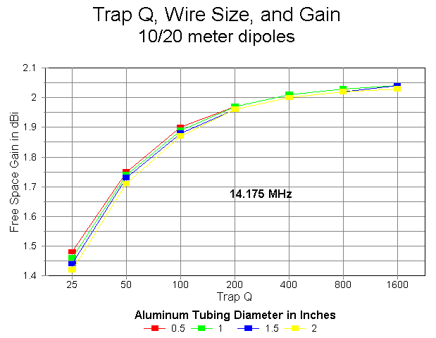
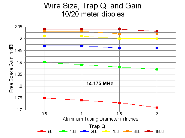
The gain values for 20 meters show an interesting negative curve for all the aluminum models, although the phenomenon is minimal at the highest Qs. Gain decreases with increases in tubing diameter. This phenomenon is due largely to the shortening of the overall length of the antenna at 20 meters, a shortening that exceeds the shortening of the 10-meter section by a factor of over 5:1 as the tubing diameter at any Q is increased from 0.5" to 2" and up.
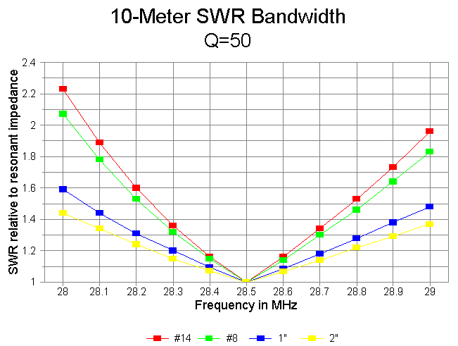
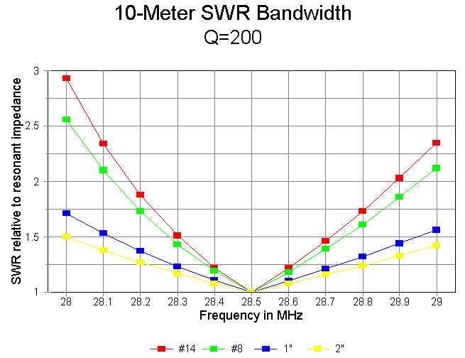
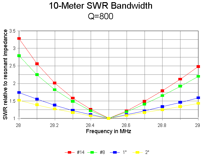
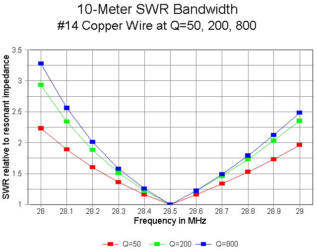
The SWR bandwidth is inversely proportional to the trap Q on 10 meters, as demonstrated in the following graph of #14 wire at Q-levels of 50, 200, and 800. Although the Q=50 model shows SWR values under 2:1 for the entire first MHz of 10 meters, the Q=800 model reduces that bandwidth to about 600 kHz. However, with antenna elements at least 0.5" in diameter, a full MHz of 2:1 SWR bandwidth is available at virtually any realizeable value of Q.
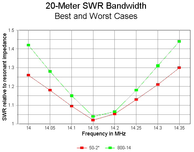
20-meter 2:1 SWR bandwidth is not a problem for any of the models at any value of Q. The following graph shows the SWR bandwidth of the best and worst cases: 2" diameter aluminum at Q=50 and #14 copper wire at Q=800, respectively. All other models tested fit within these limits.
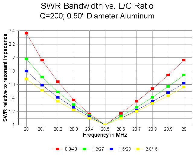
Inductance		Capacitance
in microH		in picoF
  0.8			  40.39
  1.2			  26.92
  1.6			  20.19
  2.0			  16.15
Each traps resonates at 28.0 MHz and has a Q of 200. Q=200 was selected because it is a realistic value for lumped-constant traps and because it has an internediate value in the range explored above. The antenna model uses 0.5" diameter aluminum wires in free space at frequencies of 28.5 MHz (10 meters) and 14.175 MHz (20 meters). The results of the systemmatic modeling are summarized in the following graphs.
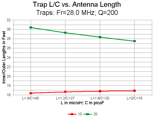
1. Antenna Length: The first graph plots the required lengths of 10 and 20 meter wires ("Inner" = 10 and "Outer" = 20). The L/C ratio makes a greater difference in element length than any other factor explored so far. The result is not surprising for 20 meters, where the L/C ratio makes a large difference in the trap reactance on the lower frequency. On 10 meters, the moderate increases in capacitive reactance at the element ends/traps (about -2000 ohms per inductance step) may be sufficient to explain the moderate increases in resonant length.
2. Antenna Gain: With increases in inductance and decreases in capacitance in the traps, the gain of the antenna follows opposing paths on 10 and 20 meters. The gain at 28.5 MHz increases as both a function of length and as a function of decreasing trap losses. In contrast, the gain at 14.175 MHz decreases as the L/C ratio grows larger mostly due to the rapid shortening of the 20 meter element extensions, but as well because of increasing (although modest) trap losses.

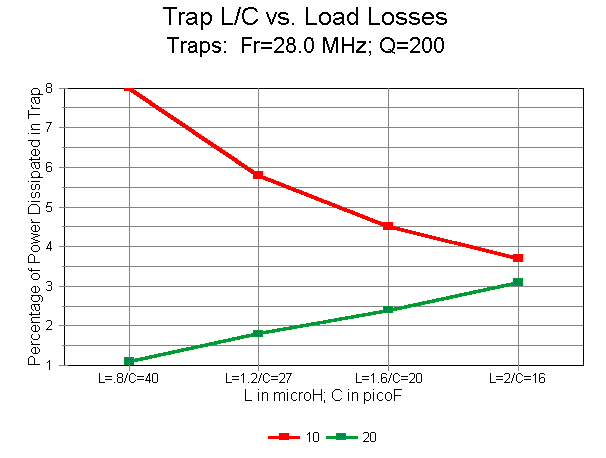
3. Trap Losses: With an increasing L/C ratio, trap power losses decrease rapidly at 28.5 MHz from 8% with the 0.8 microH inductor to 3.7% with the 2 microH inductor. As the gain chart suggests, this phenomenon is less a concern for raw element gain than it is for the construction of traps to handle the voltages and currents involved. Actual trap losses may vary from the charted figures to the degree that the capacitor in the trap has a finite Q. In the models, Q is a function of assumed coil losses. As L increases for a trap resonant at a constant frequency below the operating frequency, the parallel L-C circuit returns a capacitive reactance that also increases. As a consequence (given the constant Q), the parallel equivalent resistance also increases, resulting in lower current through the power-dissipating branch of the circuit. The increase in equivalent parallel resistance in the trap is proportional to the increase in inductance. Since capacitor losses at HF are generally presumed to be in parallel with the capacitor, any capacitor losses will also be in parallel with the equivalent parallel resistance for the coil, resulting in a lower overall parallel resistance and greater power dissipation. In a large coil with considerable inter-turn capacitance, the losses in the capacitive branch of the trap may become significant, and in extreme cases, may nullify the decreased losses shown in the graph by assigning losses only to the coil.
At 14.175 MHz, the trap losses rise from a low of about 1.1% with an inductor of 0.8 micoH to 3.1% with an inductor of 2 microH. The rise is nearly linear. Although the losses in these traps are low on 20 meters (twice the trap frequency), they promise to become significantly large, especially when the inductors reach proportions such that the resonating C consists of the stray capacitances within the coil. (This condition also promises to lower the Q of the virtual capacitor from its presumed high value as a lumped-constant component. To what degree this note pertains to the Q of the capacitance of trap assemblies employing the C along the length of coaxial cables which are also wound to provide inductance is unknown.)
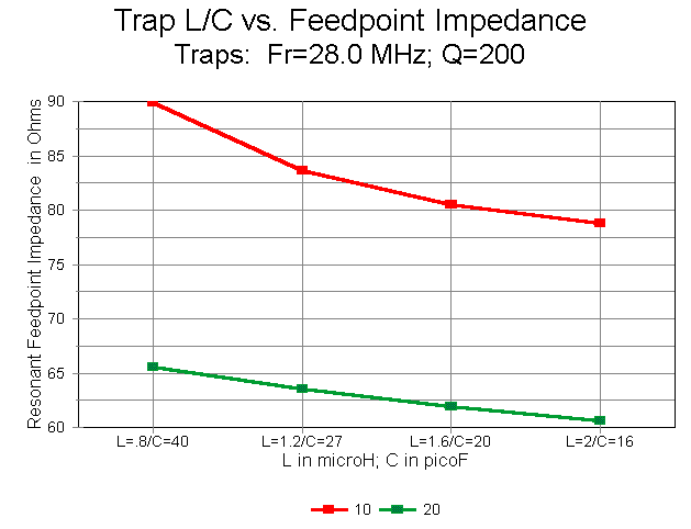
4. Feedpoint Impedance: With an increasing L/C ratio, the feedpoint impedance of the antenna tends to decrease on both the upper and lower test frequencies. However, the decreases are moderate, with the 10-meter impedance remaining largely in the 80s, and the 20 meter impedance holding in the 60s. (Throughout this exercise, the coaxial feedline of choice for the free space models would be a 70-ohm cable rather than a 50-ohm cable.)
5. SWR Bandwidth: On 10 meters the SWR bandwidth increases with an increasing L/C ratio, as shown in the graph below. All SWR figures are relative to the resonant feedpoint impedance of the element at 28.5 MHz. Only with the lowest values of inductance does the test 0.5" aluminum element fail to achieve at least a full MHz of less than 2:1 SWR.
20-meter SWR performance is not shown, since it fits entirely within the limits of the 20 meter "best-case-worst-case graph shown earlier.
By judiciously comparing the results obtained with these models at a Q of 200 and with 0.5" diameter wires with the array of models using other Q-values and other wires sizes, one may interpolate reasonable expectations for almost any size trap in a 2:1 frequency situation. However, when in doubt, the best procedure is to model the exact situation with which one is confronted.
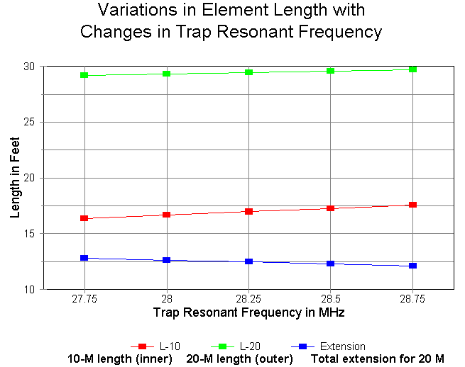
Trap Resonant		L in		C in
Frequency in MHz	microH		picoF
	27.75		  1.2		27.41
	28.00		  1.2		26.92
	28.25		  1.2		26.45
	28.50		  1.2		25.99
	28.75		  1.2		25.54
As a representative case, these traps were modeled at 10 and 20 meters using 0.50" diameter aluminum wire in free space.
The effects of variations in trap resonant frequency were minimal on the 20 meter band. 20-meter gain increased with increasing trap resonant frequencies, but by only about 0.02 dB across the span of trap frequencies tested. Feedpoint impedance changed by under 2 ohms across the same span. Changes in the variation of feedpoint resistance across the band and in the total variation in feedpoint reactance across the band were also minimal from one end of the trap frequency spectrum to the other.
Perhaps the only significant change required to re-resonate the antennas on 20 meters as trap frequency was changed occurred with respect to the length of the wire extensions beyond the traps. The following graph shows the changes in resonant 10-meter and overall 20-meter lengths for the spread of traps modeled. Note the lowest line, which indicates the sum of the two 20-meter extensions. It diminishes significantly as trap frequency increases, even though the reactance of the traps at 14.175 MHz is stable.
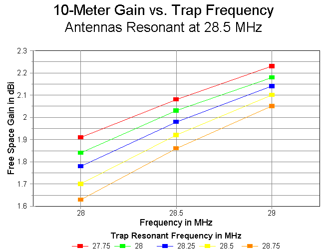
The major variations in performance occur on 10 meters. Since most folks are concerned about gain, the changes are graphed below. The total decrease in gain with increasing trap frequency averages about 0.25 dB across the span of models. It it quite likely that further gain increases would occur as the trap resonant frequency is further lowered. Note, however, that gain increases are accompanied by reductions in the 10-meter dimensions of the antenna, setting some lower size limit below the graph edge at which the effects of antenna shortening would meet to cancel the effects of lowering the trap frequency.
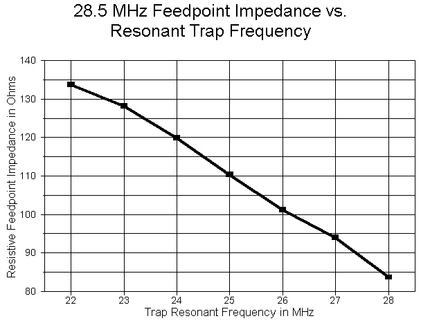
The effects of lowering the trap frequency are equally profound on the feedpoint impedance. The following chart catalogs the free space figures across the range tested.
Trap Frequency		Feedpoint Impedance at Test Frequencies (R+/-jX)
in MHz			    28.0	    28.5	     29.0
   27.75		71.00 - j49.68	85.69 + j0.02	102.1 + j47.96
   28.00		68.96 - j50.81	83.63 - j0.33	100.1 + j48.33
   28.25		67.06 - j51.58	81.76 - j0.29	98.24 + j49.13
   28.50		65.20 - j52.42	79.91 - j0.26	96.43 + j49.93
   28.75		63.37 - j53.28	87.11 - j0.24	94.69 + j50.78
 Change in Feed R	    -7.63	    -7.58	    -7.41
The impedance change is approximately 10% of the center value. Although the changes in gain and feedpoint impedance appear small when viewed in isolation, their effects on a multi-trap, multi-element antenna are cumulative. The achievment of maximum performance will therefore be a compromise between lowering the trap frequency still further and seeing the effects created by the altered geometry of the 10-meter antenna element.
How low in frequency can the resonant trap frequency go before the gain begins once more to decrease? The answer is this: a lot farther than one might initially think. I calculated Q=200 traps at every MHz marker from 22 to 28 MHz and then re-resonated the resultant 10-20 meter dipole (0.5" diameter aluminum) at each step, using 28.5 MHz and 14.175 MHz as the test frequencies. The following graph records the free space gain in dBi at 28.5 MHz.
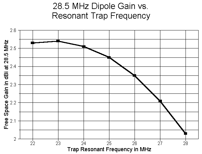
The cross-over point is around 23 MHz or just slightly lower. (Remember that because trap variables interlock, this frequency may vary with trap Q, wire size, and a number of other factors.) The antenna length varies regularly at about 1.32'/MHz for the 10-meter section and 0.88'/MHz for the outer or 20-meter dimension. (The slower decrease for the 20-meter section actually represents a lengthening of the 20-meter extensions.) As the following graph shows, the 28.5 MHz resonant feedpoint impedance also climbs as the resonant trap frequency decreases.
Although the gain increase at 10 meters is real, several factor mitigate against resonating a 10-meter trap as low as 23 MHz. First, the interaction between the 10 and 20 meter segments of the antenna grows touchy from about 24 MHz down so that small changes in one area require changes in the other. Second, the 20-meter gain continues to drop at an increasing rate so that with a 22 MHz trap, the free space gain is only 1.68 dBi. Third, the 14.175 MHz resonant feedpoint impedance decreases as the resonant trap frequency decreases, driving the 10-meter and 20-meter impedances further apart. Consequently, even for straightforward dipole operation, the final selection of a trap frequency will be a compromise offering the best combination of gain figures and usable impedances for both antenna sections.
The results (along with the 10-20 meter combination for comparison) appear in the following table.
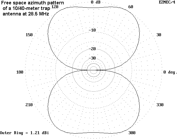
Combo	Frequency	Gain	Feedpoint Z	% Power dissipated
	in MHz		in dBi	(R +/- jX ohms)	 in trap

10/15	28.5		1.94	76.16 - j0.79	 4.53
	21.225		1.97	70.04 + j0.06	 2.69

10/20	28.5		2.03	83.63 - j0.33	 5.83
	14.175		1.98	63.56 - j0.72	 1.76

10/40	28.5		1.21*	79.61 - j0.73	 5.92
	 7.15		2.03	62.79 + j0.50	 0.87
The progression of figures appears regular and reasonable in every category except one: the 10-meter gain figure in the 10/40 meter combination. As the following free space azimuth pattern shows, the anticipated figure-8 pattern is distorted into a pair of opposing molars, with an overall lower gain.
The reason for the pattern distortion becomes plain from an examination of the 10-meter antenna current levels, especially in the 40-meter extensions.
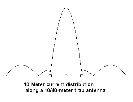
Each extension is longer than 1/2 wl so that current may form a nearly sinusoidal curve with peaks about 10% of the overall antenna peak current. These peaks are sufficient to distort the anticipated radiation pattern, with some field cancellation in the areas where radiation normally peaks. Virtually any trap element with a frequency ratio approaching 4:1 will share this property. Therefore, every proposed trap antenna design requires individualized modeling and testing to ensure desired results.
Much work awaits in the wings. The effects of traps on multi-element antennas and the use of multiple traps in each element have not been explored here. There is also another entire class of trap antennas wherein the trap is not resonant near any of the intended ham bands. On the use of traps that are not resonant near or within any band of antenna use, Al Buxton, W8NX, has likely done the most work.
If anything, investigations like this one should go some way toward correcting over-simplified views of traps. Traps and their effects on antennas using them form a fascinating complex landscape of their own.
Updated 7-12-97. © L. B. Cebik, W4RNL. Data may be used for
personal purposes, but may not be reproduced for publication in print or
any other medium without permission of the author.