 Close-Spaced Wires: MININEC vs. NEC-4
Certain problems encountered with modeling Tee matches and open sleeve coupled elements led me to explore more systematically the possibility of a further systematic error. Apparent anomalous results occurred when antenna wires in NEC-4 were placed in close proximity, despite following recommended guidelines of aligning the segments of the wires to the degree possible.
Therefore, I performed a simple modeling test of modeling a 1" diameter aluminum dipole for 14 MHz. I then created 3 different models of resonant 21 MHz dipoles, all aluminum, but having diameters of 0.5, 1.0, and 1.5 inches.
In separate tests, I placed each of these 21 MHz dipoles in proximity to the 14 MHz dipole at distances of 2 through 12 inches in 2" increments. The 2" spacing was deemed the least permissible that would prevent the wire surfaces from touching. For each test, the 14 MHz fed dipole was reresonated and the gain figure recorded. As in past tests, resonance is defined as a feedpoint reactance of under 1 ohm. Since the test was designed to see the effect of the shorter wire on the longer, the original lengths of the 21 MHz antennas were preserved for each size throughout the test runs.
The tests were performed on both MININEC 3.13 within ELNEC 3.0 and on NEC-4 within EZNEC Pro. Likewise, the lengths of the 21 MHz elements differed from a half inch for the smallest diameter element to about 1" for the largest.
The 14 MHz antenna used 34 segments in MININEC and 35 segments in NEC-4. The 21 MHz element was assigned 22 segments in MININEC and 23 in NEC-4. This segmentation aligned the segments quite reasonably. Since this segmentation already exceeds common practice in linear antenna design, convergence testing was not systematically undertaken, although the same performance curves appear with both fewer and more segments per half- wavelength.
All gain figures were recorded as free space gain in dBi. With respect to closely spaced elements, there are two gain figures of note: the in-plane gain and the out-of-plane gain. The former is the maximum gain of the dipole and extra wire with the wires in line with each other. The latter is the gain in a direction broadside to a plane through the two wires. Out-of-plane gain will ordinarily be less than in-plane gain, although in- plane gain will show a front-to-back ratio approximately double the difference of the two gain figures.
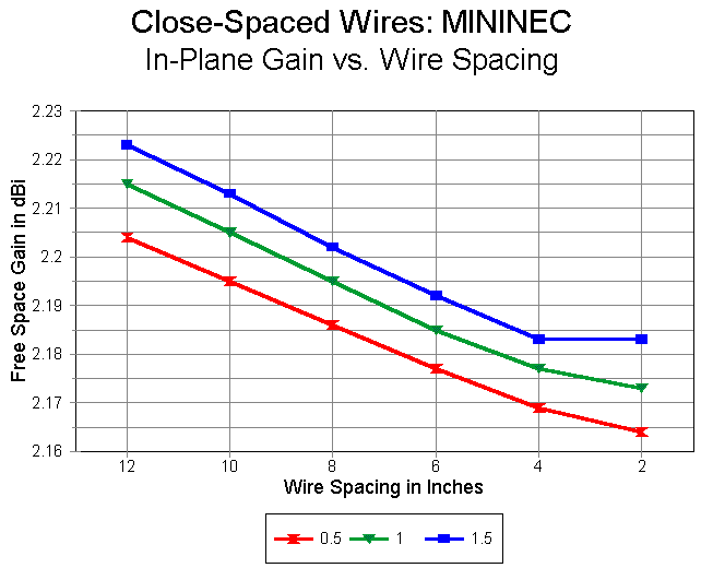
The tests were first run with MININEC. The following graph shows the in- plane gain for each diameter of extra wire as the distance between elements is decreased from 12 to 2 inches. Most notable in the graph is the flattening of the curves as the spacing reaches 2 inches, despite a reasonably linear progression to that point.
Some of the reason for the flattening appears in the follow graph, which records the out-of-plane gains for the wire pairs over the same range of spacings. As the distance reaches 2 inches, the gain begins a steep increase. To all appearances, the two wires begin at this close proximity to act as a single fat wire. Whatever the true accuracy of the MININEC results, they do at least accord with normal expectations for closely spaced wires.
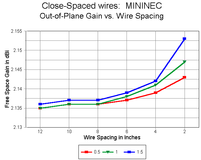
The MININEC results acquire a further degree of confidence when one examines the range of variation. The total in-plane gain variation is less than 0.06 dB, while the out-of-plane gain variation is less than 0.02 dB.
The gain figures encountered with NEC-4 show a quite different pattern. For example, the in-plane figures, shown in the following graph, show an overall increase through the same range of distances separating the two wires. The range of variation between 12 and 6 inch spacing is about 0.04 dB, but over the entire span of separations, the range increases to more than 1 dB.

Equally notable is the fact that NEC-4 shows the highest gain when the two wires have the same diameter. How exact this equality is cannot be determined by this test, since the secondary wire diameters are widely separated.
A similar curve accompanies the figures for out-of-plane gain. There is a larger spread of gains in the 12 to 6 inch range (0.06 dB), but the overall gain increase with closing separation is greater than 1 dB.
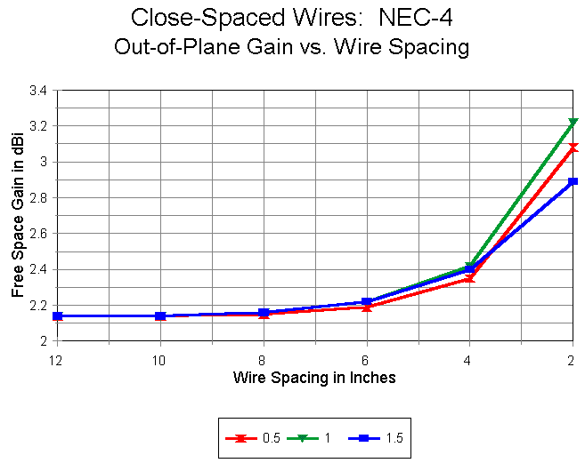
At least for case at hand, which uses a secondary wire about 2/3rds the lengths of the fed wire, there appears to be a critical distance at which anomalous results begin to emerge. The following two graphs compare the in-plane and out-of-plane gains for MININEC and NEC-4 when the elements have the same diameter.
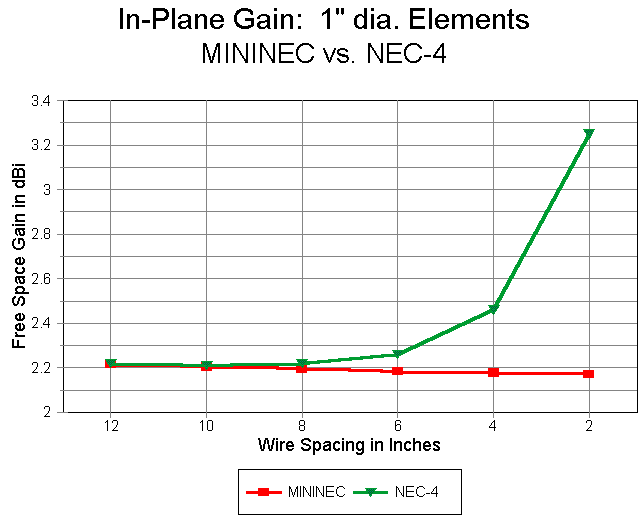

Careful examination of the graphs shows that the curves overlap for spacing of 12 inches and 10 inches. However, between the 10" and 8" marks, the curves begin to diverge ever more radically.
It is also interesting to contrast MININEC and NEC with respect to the required length of the 14 MHz element for resonance with the 21 MHz wire in close proximity. As the following graph shows, once we allow for the slight length variation of the 2 systems, the MININEC curve is much steeper than the NEC-4 curve at the closest spacings. However, the curve is in fact smoother than the NEC-4 curve, as the break in the NEC-4 curve at 6" is real and not a function of rounding.

Moreover, there are also interesting differences in the feedpoint resistance curves. As noted, the 14 MHz elements were resonated to less than 1 ohm reactance. In the graph below, the MININEC feed resistance curve shows a small dip at the 8" spacing and then a smooth progression upward. In contrast, the NEC-4 curve shows a rapid progression downward past the 6" point. These same phenomena occurred with scaled VHF antenna models.

These tests are only the beginning of a systematic exploration of the differential in gain and other figures from the MININEC and NEC-4 modeling systems. Here are a few further developments of these tests.
Scaling: Scaling all the dimensions of the situation by a factor of 10 upward--including frequency, lengths, and wire diameters--produces curves that tightly fit those produced so far. This applies to both the MININEC and NEC-4 curves. The resonant 140 MHz 0.1" diameter aluminum wire spaced from 1.2 to 0.2 inches offsets are so slight, relative to the resonant 14 MHz 1.0" diameter aluminum wire spaced from 12 to 2 inches, that they would not appear in any form of graphing.
Wire Length Ratios: The 20-meter antenna with a 15 meter wire forms a length ratio of 3:2. A series of NEC-4 runs was made to compare this ratio of wire lengths to wires with a 2:1 ratio and with a 4:3 ratio, focusing on wires of the same diameter (1" aluminum). The results appear in the following graph.
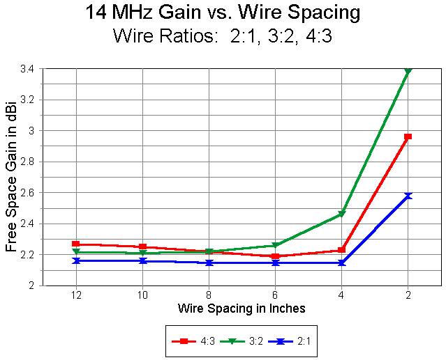
Interestingly, the departure of the gain from a typical MININEC curve is greatest when the fed wire is about 50% longer than the closely spaced unfed wire, at least when the wires have the same diameter. Once more, the widely separated selection of test ratios does not lend precision to this conclusion. Since wires having a 1:1 diameter ratio appear to have a greater departure from typical MININEC curves than other wire diameter ratios, it would appear that by chance, my initial tests have fallen into at least the ball park of greatest deviation.
Close Spacing and Multi-Element Arrays: The effects of a close-spaced wire on a dipole model are only indicators, but not predictors of the effect of a close-spaced wire on a parasitical beam model. Indeed, the disparity of gain and other performance figures between MININEC and NEC-4 might well be either quite profound or quite trivial.
I quickly created a 3-element Yagi model to check the potential for divergent readouts. An extra wire was placed ahead of the driven element at the spacing indicated in the tables. The results were as follows:
               MININEC                       NEC-4
Space     Gain   F-B     Z           Gain    F-B       Z
No wire   8.03   24.97   26.9+j2.1   8.08    27.94  26.6+j4.8
2:1 Ratio
 4"       8.02   24.86   26.9+j1.1   8.68    27.81  23.4+j3.4
 7"       8.03   24.87   27.0+j1.3   8.26    27.84  25.7+j3.9
10"       8.03   24.88   27.0+j1.4   8.14    27.85  26.4+j4.1
13"       8.03   24.88   27.0+j1.5   8.10    27.86  26.6+j4.2
16"       8.03   24.89   27.0+j1.5   8.09    27.88  26.7+j4.2
3:2 Ratio
 4"       7.88   24.77   28.0+j0.0   9.35    27.68  20.3+j1.8
 7"       7.96   24.79   27.6+j0.4   8.61    27.76  24.1+j2.6
10"       8.00   24.82   27.5+j0.6   8.33    27.81  25.6+j3.0
13"       8.01   24.84   27.4+j0.7   8.21    27.86  26.4+j3.2
16"       8.02   24.87   27.3+j0.7   8.15    27.91  26.7+j3.3
4:3 Ratio
 4"       8.20   24.74   26.2-j1.0   6.81    27.93  37.7+j3.3
 7"       8.12   24.78   27.0-j0.5   7.34    27.91  33.1+j3.6
10"       8.08   24.82   27.4-j0.3   7.67    27.93  30.6+j3.4
13"       8.06   24.87   27.5-j0.2   7.85    27.98  29.2+j3.1
16"       8.05   24.91   27.6-j0.1   7.94    28.04  28.5+j3.0
The tables hold some surprises. First, the NEC-4 gain values diverge more radically than the MININEC numbers, especially for the 2:1 ratio of driven element to extra wire. Second, for the 3:2 and 4:3 ratios, MININEC and NEC-4 gain numbers diverge in opposite directions. Nonetheless, the NEC-4 figures are still farther from the "no-wire" baseline than those of MININEC. Third, unlike the simple dipole examples, the gain of some models may decrease in the presence of the extra wire.
Before you draw any conclusions, let me reveal that the above table is erroneous. It is based on a defective model that is nevertheless all too common in amateur modeling practice. All 4 elements, the 3 20-meter elements plus the added wire, whatever its length, were assigned 10 segments in MININEC and 11 segments in NEC-4. The segments do not align, which is especially important in NEC, but not insignificant in MININEC with some models. Moreover, neither model converges well with models having twice as many elements. These practices cast doubt on the reliability of the results.
So I reset the models, using 34 segments per 20 meter element (35 in NEC), and a proportionate number for the shorter extra elements. Convergence with models of twice the segmentation was excellent, with a gain difference of about 0.01 dB. Running these models resulted in a change of extra- element spacing to begin at closest with 3" rather than 4." Despite the closer spacing, the following results developed.
               MININEC                       NEC-4
Space     Gain   F-B     Z           Gain    F-B       Z
No wire   8.01   26.66   28.4+j5.4   8.12    26.86  26.3+j6.6
2:1 Ratio
 3"       8.01   26.64   28.9+j4.1   8.40    26.72  25.0+j5.2
 6"       8.01   26.65   28.7+j4.5   8.15    26.74  26.4+j5.8
 9"       8.01   26.66   28.7+j4.7   8.12    26.75  26.5+j6.0
12"       8.01   26.67   28.6+j4.8   8.12    26.77  26.5+j6.0
15"       8.01   24.68   28.6+j4.8   8.12    26.78  26.5+j5.2
3:2 Ratio
 3"       8.00   26.52   29.3+j3.7   8.33    26.62  26.0+j4.1
 6"       8.00   26.57   29.2+j3.7   8.14    26.66  27.0+j4.9
 9"       8.00   26.61   29.1+j3.6   8.12    26.69  27.0+j5.2
12"       8.00   26.65   29.1+j3.3   8.12    26.73  26.9+j5.3
15"       8.00   26.70   29.1+j2.6   8.12    26.76  26.9+j5.3
4:3 Ratio
 3"       8.01   26.73   30.0+j1.6   7.40    26.69  33.3+j3.9
 6"       8.01   26.80   29.8+j2.6   8.03    26.66  28.3+j4.4
 9"       8.01   26.87   29.7+j2.9   8.10    26.70  27.7+j4.5
12"       8.01   26.95   29.6+j3.1   8.11    26.76  27.5+j4.6
15"       8.01   27.02   29.6+j3.1   8.12    26.82  27.4+j4.7
A comparison of the tables shows two very significant facts. First, when models are developed carefully, rather than casually, any tendencies for any program to deliver potentially erroneous results is lessened. All figures for each length of extra element are far more tightly grouped.
Second, despite the tighter grouping, the same types of curves develop as with the casual model. To two decimal places, MININEC results are totally stable, although the third decimal place shows the mathematical progressions that appeared in the earlier model. Likewise, NEC-4 progressions show increasing gain with closer spacing for the two shorter lengths of extra elements and reduced gain with closer spacing for the longest extra element. In general, the instability with the figures occurs when spacing are closer than 6 to 9 inches at 14 MHz. Maximum deviations from the norm run from 0.2 dB to 0.5 dB for the example used. While less than with the casual model, the amounts of deviation from the normal can be significant, especially when compared to the extremely stable MININEC figures.
Conclusion: Each of these directions of research will require many more runs of wire combinations at many different frequencies before precise conclusions and systemmatic formulations of the MININEC/NEC-4 differentials can be drawn. I presume such work exists within appropriate research institutions and has simply not yet reached the community of modeling program users. At least, none has yet crossed my admittedly limited path.
Nonetheless, the simple test performed here is sufficient to suggest strongly that users of NEC-4 model closely spaced wires with great caution. If NEC-4 proves to be the anomalous case, then it may not be possible to routinely model closely spaced antenna structures with any presumption of accuracy with respect to resulting gain figures.
On the other hand, if MININEC proves to be more accurate in such cases, then perhaps it is time that an enterprising programmer undertook an effort to reprogram MININEC to a. release it from its 256-segment limitation and b. to enable the matrices to execute far more rapidly than in the current version.
(It would be useful to be able to compare these results with the Rockway- Logan revised MININEC, but the copy I purchased is apparently flawed so that some key modules will not work after 1 or 2 runs and must be reinstalled, even then with no assurance of working results. Moreover, the interface lacks the degree of user convenience associated with such diversely styled programs as AO and ELNEC, thus lengthening the time required for setting up even simple antenna models. However, the new MININEC calculating engine within an AO, ELNEC, or NEC-Win interface would be interesting to test thoroughly.)
As with all such tests, reasonableness of the appearance of results is not
a sufficient validation of a modeling system. Nonetheless, it appears safe
to note that closely spaced wires modeled in NEC-4 should always be
approached with more caution than confidence.
Updated 9-24-97. © L. B. Cebik, W4RNL. Data may be used for personal purposes, but may not be reproduced for publication in print or any other medium without permission of the author.