 Part 5: Shorties, Double-Wides, and Twins
In our final episode, we shall be even more hurried, and hence must confine ourselves further. We shall look at shortening techniques for some of the SCVs, at open-face double-wide versions of them, and at the basics of parasitical techniques applied to the SCVs. We can only cover the ground by sticking to one band (80), one soil type (Average: C = 0.005 S/m; DC = 13), and limited variations. Again, I hope the data will be enough to let you extrapolate to your specific needs.
Even some shortening can be beneficial. For reasons that will become apparent, I have limited discussion to 3/4-size deltas, which--at 3.6 MHz-- become 72' wide by 62' high. The 21' height saving alone can make the difference between the antenna being feasible and being impossible.
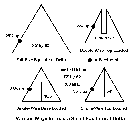
Figure 1 shows perhaps the three most common forms of loading the shortened delta in order to make it resonant once more. In Low Band DXing, ON4UN shows some of these and other loading schemes.1 In some respects, all three techniques are varieties of one technique: adding wire to the highest impedance point possible in order to sustain the high current parts of the antenna for maximum field strength.2 However, the techniques show some interesting differences.
One of those differences is the feedpoint, which is distinctly higher up the side for the double-wire top-loaded model than for the other two models. For maximum vertically polarized radiation, the feedpoint was chosen to yield the lowest take-off angle possible (with verifying checks upon the remnant horizontal field to confirm minimal field strength in that polarization). One can fine tuning this point in models by selecting the feedpoint so that the final horizontal field (which is a cloverleaf in azimuth patterns) is as symmetrical as possible.
Part of the reason for the higher feedpoint up the side of the double- wire top-loaded model is the current distribution in the loading wire assembly. The current magnitude in each of the two wires at the apex is about 0.8 of the source current. In both the single-wire loaded version of the antenna, the current is about double this value.
        A Comparison of Shortened Equilateral Delta 80-Meter Loops

Antenna Full Size Delta   Double Wire Top    Single Wire Top    Single Wire Base
             Loop              Loaded              Loaded             Loaded
Ht    Gain TO   Feed Z    Gain TO   Feed Z   Gain TO   Feed Z   Gain TO   Feed Z
feet  dBi  deg. R+/-jX    dBi  deg. R+/-jX   dBi  deg. R+/-jX   dBi  deg. R+/-jX

10    1.28  22  196+j41   0.55  23  87+j39   0.62  23  76+j33   0.33  22  40+j12
20    1.48  20  167+j 1   0.80  21  72+j12   0.86  21  65+j 7   0.71  21  32+j 0
30    1.58  18  147-j13   0.92  20  63+j 3   0.96  20  57-j 2   0.81* 19  28-j 4
40    1.62* 17  132-j18   0.97* 18  56+j 2   0.99* 18  51-j 6   0.80  17  25-j 6
50    1.59  16  122-j17   0.96  17  51-j 2   0.97  17  47-j 7   0.74  16  23-j 6
60    1.50  15  114-j13   0.89  16  47-j 2   0.89  16  43-j 7   0.62  15  22-j 6
70    1.34  14  110-j 8   0.76  15  44-j 1   0.75  15  41-j 5   0.47  14  21-j 5

Note 1:   Full-size delta loop:  96' baseline, 83' height; shortened delta
          loops (3/4 full size):  72' baseline, 62' height.
          Double-wire top load is 1' wide by 47.4' long; single wire top
          load is 54' long; single wire base load is 46.5' long.
          All antennas: #12 AWG copper wire.  Height entry: baseline height
          above ground.  Design frequency: 3.6 MHz.
          All antennas over average soil (C=0.005 S/m; DC=13).

Table 1.  A comparison of shortened equilateral delta 80-meter loops.
Table 1 shows the results of modeling each loaded delta, along with a full size equilateral delta for comparison--all over average soil. Immediately apparent is the fact that the top-loaded deltas require the same baseline height as the full size delta for maximum gain. Although the base-loaded delta finds its maximum gain level 10' lower, its overall gain is also lower than either of the top-loaded models. Between the top-loaded models, there is little if anything to choose. Both provide close to a 50- Ohm match (with the base-loaded model having about half the feedpoint impedance of the top-loaded models). The gain of the best loaded delta is down by two-thirds of a dB from the full-size model, an amount which is usually not too significant operationally.
Like the full-size right-angle delta, which has a feedpoint impedance and 80-meter height that closely accord with those of the loaded deltas, the feedpoint resistive component does not change radically across the 80- meter band. This makes the loaded delta a candidate for remotely tuned series capacitance compensation for an antenna designed to have inductive reactance at all across the band or across some part of the band of interest. Models also suggest that the antenna gain increases more rapidly as the antenna is "oversized" than is the case with dipoles and similar horizontally polarized antennas.
The limitation on the delta used for the modeling sequences is that the single-wire top-loading element had to fit within the delta. In practice, where many delta users install them at angles other than vertical, the wire can be almost any length.3 (However, heed ON4UN's warning about the high voltage on the end of this wire.) Where the wire may seem to require more length than the delta permits, the end can be split, folded back, or coiled, although each of these techniques may increase the need for very careful adjustment.
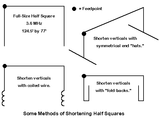
The techniques just listed are more commonly applied to shortened half squares, as illustrated in Figure 2. Half squares tend to lose the least performance when the length of the phasing line is left in tact and only the length of the vertical members is shortened. I ran a series of free space models to check the performance losses with shortening. The full size half squares with 77' verticals showed a gain of 4.6 dBi and a resonant feedpoint impedance of about 63 Ohms. Using the symmetrical hat technique of loading, I shortened the verticals to 60' with horizontal spikes running 10' each way from the element ends. The gain dropped to about 4.45 dBi, with a decrease in the feedpoint impedance to 57 Ohms resistive. Enlarging the hat spikes to 20' each permitted the verticals to be only 46' long: the gain dropped to about 4.1 dBi and the feedpoint impedances decreased to 45 Ohms resistive. Similar decreases could be expected over ground relative to a full-size half square. The design question remaining would center on choosing a compromise between the top height for the lowest take-off angle and the bottom height for maximum gain from the shortened antenna.
The key element in successfully obtaining maximum performance from a shrunken SCV is to place the loading at the high voltage, high impedance portion of the antenna, leaving the high current portions as undisturbed as possible. In addition, design work should also include pre-construction modeling exercises to locate the feedpoint at the position which produces maximum vertically polarized radiation and minimum horizontally polarized radiation--assuming that one wishes SCV-type performance.
At the other end of the scale from the shorties are the side-by-side double SCV antennas. Versions have been built for each of the major SCV types, so that there are double-humped deltas, open-face double rectangles (also called open double magnetic slot antennas), and double half squares (called bobtail curtains). Each has a tale of its own to tell.
The Double Right-Angle Delta. Figure 3 illustrates the design and resonant dimensions of a double right-angle delta cut for 3.6 MHz.4 The single right-angle delta is shown for comparison. Very little difference exists between the dimensions of each of the double's two triangles and the one trinagle of the single delta.
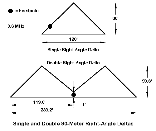
The key difference lies in the position of the feedpoint. Where the two triangles would meet in the middle, the feedpoint is place between the baseline and the lowest point of the triangles' upper wires. Due to the balance within the overall system, horizontal radiation does not radically increase relative to that within a single delta with optimal feedpoint placement. Moreover, the feedpoint is compatible with a coaxial feed system.
     A Comparison of Single- and Double-Humped Right-Angle Delta Loops

Antenna:  Single Right-Angle Delta       Double Right-Angle Delta

Height    Gain  TO   Feed Z              Gain  TO   Feed Z
feet      dBi   deg. R+/-jX              dBi   deg. R+/-jX

10        1.63  24   97+j42              3.97  23   54+j22
20        1.94  22   81+j12              4.08* 22   47+j 8
30        2.08  20   71+j 1              4.04  20   43+j 3
40        2.14  18   63-j 4              3.97  18   40-j 0
50        2.15* 17   57-j 5              3.89  17   37-j 2
60        2.09  16   53-j 4              3.79  16   35-j 2
70        1.96  15   50-j 2              3.66  15   33-j 1

Note 1:   Full-size right-angle loop: 120' baseline, 60' height; double
          right-angle loop:  242' baseline, 60.5' height.  All antennas:
          #12 AWG copper wire.  Height entry: baseline height above ground.
          Design frequency: 3.6 MHz.  All antennas over average soil
          (C=0.005 S/m; DC=13).

Table 2.  A comparison of single- and double-humped right-angle delta
loops.
Other differences emerge from a comparison of the performance at various heights of the single and double right-angle deltas. Table 2 compares the antennas between 10' and 70' baseline heights over average soil. Two data point stand out. First, a properly constructed double delta is capable of almost 2 dB gain over a single delta. Second, the baseline height for maximum gain is much lower for the double delta than for the single--some 30' lower. However, this extra gain and lower height requirement are purchased at the price of an antenna nearly 240' long that requires at least two high support points. Whether or not this defeats the value of the delta, whose single-hump version requires only one high support point, is a builder judgment.
The Double Open Rectangle. K4VX brought the double open magnetic slot--or the double rectangle, for simplicity--to amateur antenna most recently.5 When optimized for gain in free space, the dimensions shown in Figure 4 are best for 3.6 MHz.
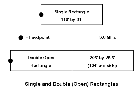
The free space gain for the double rectangle was 5.5 dBi, compared to about 5.0 dBi for the double delta. The half dB advantage of the double rectangle also shows up over ground, as the figures in Table 3 demonstrate. However, the double rectangle requires considerably more baseline height to achieve maximum gain than the double delta. At a height of 20' for the baseline of each, performance is quite similar. Compared to the single rectangle, the double rectangle shows a gain advantage of about 1.5 dB, which is also 1 dB higher than the K5RP double-wire rectangle reviewed in an earlier episode.
            A Comparison of Single and Double Rectangular Loops

Antenna:  Single Rectangle               Double (Open) Rectangle

Height    Gain  TO   Feed Z              Gain  TO   Feed Z
feet      dBi   deg. R+/-jX              dBi   deg. R+/-jX

10        2.21  25   50+j38              3.72  25   109+j57
20        2.76  23   40+j15              4.23  23    81+j15
30        2.98  21   34+j 7              4.44  22    68+j 0
40        3.08  20   30+j 4              4.53  20    59-j 5
50        3.11* 18   27+j 2              4.56* 18    53-j 7
60        3.08  17   25+j 2              4.54  17    48-j 7
70        3.01  16   23+j 2              4.46  16    45-j 6

Note 1:   Single rectangle: 110' long, 31' high; double rectangle:  208'
          long, 26.8' high.  All antennas: #12 AWG copper wire.  Height
          entry: baseline height above ground.  Design frequency: 3.6 MHz.
          All antennas over average soil (C=0.005 S/m; DC=13).

Table 3.  A comparison of single and double rectangular loops.
With dimensions of the rectangle optimized for gain, the preferred feedpoint position is at the center of one end of the assembly. At the height of maximum gain, the feedpoint impedance is about 53 Ohms, whereas the impedance of the antenna if fed on the center wire is only about 17 Ohms.
The double open rectangle is about 208' long, some 30' shorter than the corresponding double delta. Moreover, it is over 30' shorter in height. Thus, the high point for maximum gain installations of both antennas is quite similar (about 80'), even though the baseline of the rectangle needs to be higher.
The Bobtail Curtain. Of all the double SCVs, the bobtail curtain has the highest gain.6
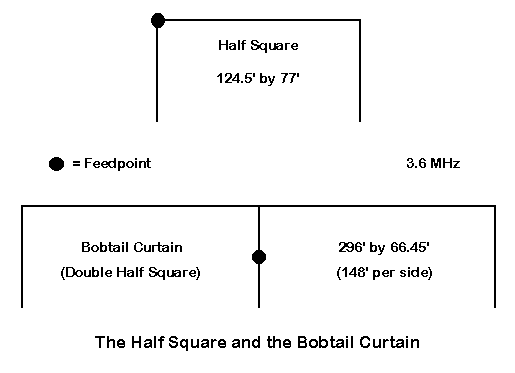
With the gain-optimized dimensions shown in Figure 5, the antenna has a free space gain of over 6.4 dBi. The gain also appears over ground, as shown in the figures in Table 4. The gain is well over 1.5 dB higher than for the half square and a full dB higher than for the double open rectangle, when each is place at the correct height for maximum gain. In fact, with maximum gain of the bobtail appearing over average soil at a minimum height of 15' or so, the maximum required height is once more about 80' above ground. (In other words, all three double SCVs require about the same upper height to achieve maximum gain.)
          A Comparison of the Half Square and the Bobtail Curtain

Antenna:  Half Square               Bobtail Curtain

Height    Gain  TO   Feed Z         Gain  TO   Feed Z
feet      dBi   deg. R+/-jX         dBi   deg. R+/-jX

 5        3.75  20   81+j19         5.38  21    75+j39
10        3.79* 19   75+j 8         5.45  20    68+j22
15        3.79* 18   71+j 2         5.47* 19    64+j12
20        3.76  18   68-j 0         5.45  18    61+j 7
25        3.71  17   66-j 1         5.42  18    58+j 3
30        3.63  16   64-j 3         5.36  17    53-j 2

Note 1:   Half square: 124.5' long, 77' high; bobtail curtain:  296' long,
          66.45' high.  All antennas: #12 AWG copper wire.  Height entry:
          baseline height above ground.  Design frequency: 3.6 MHz.  All
          antennas over average soil (C=0.005 S/m; DC=13).

Table 4.  A comparison of the half square and the bobtail curtain.
Unlike the other double SCVs, whose dimensions are close to a simple doubling in length of their single SCV parents, the bobtail requires significant refiguring of the half square dimensions. The dimensions optimized by modeling show a longer and lower antenna: about 296' long and 66.45' high. These figures are close to the proportions recommended by SM4CAN, as cited in ON4UN's book.7 For the added length, one acquires nearly 4 dB gain over a single full size equilateral delta at its optimum height.
Feeding the bobtail is best done at the center wire. The high impedance base point of the wire can be fed via a parallel tank circuit. However, the impedance at the center of the wire is close to a coax match. If the height of the antenna yields too high an impedance at this point, one can simple select a higher point on the wire. With the model shown at the height for maximum gain, the top of the center wire shows an impedance of about 33 Ohms. Hence, between the top and the center, there is a good coax matching point for almost any installation.

A comparison of azimuth patterns--each at the elevation angles of maximum radiation when the antenna is set at the height for maximum gain-- can reveal something further about the differences among the double-wide SVCs. See Figure 6. As the gain of the double-wides increases, the side- rejection also increases. In its maximum gain configuration, the bobtail actually begins to show a side "bulge" in its pattern. For maximum side rejection, the bobtail can be made slightly taller and less lengthy, if a little less gain is acceptable.
Where a higher degree of directionality is needed, one can press the SCVs into parasitical service with fair ease. Deltas will show a directional pattern with some front-to-back ratio and a little gain, and they may be placed at angles sloping from a cross bar placed near the top of a single existing tower. However, the most improvement occurs when one moves up to the half square, and we shall use this SCV as the basis for these notes.
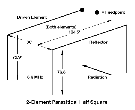
Figure 7 sketches a feasible 2-element parasitical beam for 3.6 MHz. One useful guideline for half-square beams is to leave the horizontal length of the two elements the same (and to place them at the same height). Adjust the beam properties by altering the lengths of the verticals. In the sketch, the spacing was chosen for convenience: 30' provides a feedpoint impedance that varies between 50 and 55 Ohms as the bottom height of the antenna is raised from 13 to 23 feet (top height range: 87 to 97 feet). A wider spacing would add some gain to the array.
The forward gain of the beam over ground is about 6.7 dBi in the favored direction, with about 18 to 23 dBi front-to-back ratio, depending upon height. These figures are for an elevation angle of maximum radiation that runs between 17 and 18 degrees. The beamwidth is about 65 degrees between -3 dB points.
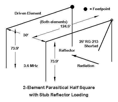
With vertical legs of different lengths, the beam just described is fixed in one direction. The beam becomes reversible if we make both the driven element and the reflector legs the same length. By adding a shorted stub of 50-Ohm coax to the reflector (about 25' for this particular array), as shown in Figure 8, the beam produces the same range of feedpoint impedances, the same range of front-to-back ratios, and the same gain (within 0.1 dB) as the beam in Figure 7. Since the stub may be brought to a center point between the elements, twin stubs may run from each element. With simple switching of both the center conductor and the outer braid, one line becomes a shorted stub and the other becomes just a part of the feed system for the beam. The result is a reversible beam.
If the builder prefers, he can use appropriate lengths of open-ended transmission line to place the stub junction point closer to the ground. Even shorted stubs longer than 1/2 wavelength can be used for a ground- mounted junction box. However, the longer the stub, the greater its losses, resulting in a little loss of front-to-back ratio (mostly). Alternatively, the beam can be fed with parallel transmission line, with the stubs cut to suit the higher impedance, higher velocity factor line.
Parallel transmission line becomes more attractive as a feed system for those who wish to operate over large regions of the band. The 80-meter model shows a fairly small frequency range for good beam properties. Parallel transmission line to an ATU allows use of the antenna across the entire band, with beam properties set for some "special" segment. Moreover, with only a little more complexity, the reversible beam can be configured for phased feeding to change the properties of the resulting field.
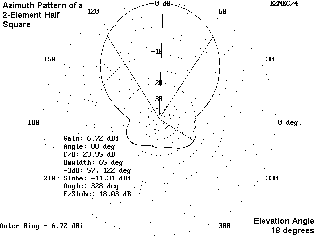
Since the half square is fed at one corner, the azimuth pattern will be slightly tilted, as shown in Figure 9. The two-degree difference in the forward direction is less likely to be noticed than the differential to the rear.
With a maximum gain of about 6.6 to 6.7 dBi over average soil, the advantages over a standard wire Yagi may not be immediately apparent. A wire Yagi will have dimension fitting wholly within the width of the horizontal portion of the half square, without the need for vertical legs. When placed at the same height as the half square top wire, the Yagi will show up to 9.4 dBi gain.
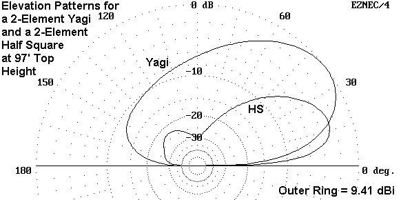
Figure 10 shows a comparison between the elevation patterns of the Yagi and the corresponding pattern of the half square beam. The SCV beam shows low angle radiation several dB stronger than the horizontal Yagi. However, perhaps the real advantage of the SCV beam for DX work is most apparent where the Yagi shows high gain and the half square beam shows little or none. The SCV not only rejects signals to the rear by 10 dB more than the Yagi, but as well the forward lobe is relatively unresponsive to high-angle signals above 30 degrees elevation.
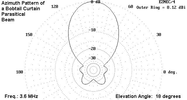
For those with acres of open land or those who simply like to dream of large wire arrays, the bobtail curtain is also open to treatment as a parasitical beam.8 Using the horizontal dimensions of Figure 5, we can cut driver verticals to 64.4' and reflector verticals to 66' to obtain a 30'- spaced array with some remarkable properties. With a top height of 81.5' (plus or minus a bit), we obtain the azimuth pattern of Figure 11, with a 50-Ohm feedpoint impedance if the center leg is fed at the middle of its vertical length. With a gain of over 8 dBi at a low angle and a worst-case front-to-rear ratio of about 25 dB, the antenna is highly directional. Its narrow 44-degree beamwidth does suggest application in specific directions rather than more general operation. The bobtail beam is susceptible to reversibility in a manner similar to that used with the half square.
Remember that in our modeling look at each of the SCV types, we discovered that we cannot automatically scale an antenna from one band to another and expect the same performance or feedpoint impedance. The antennas in this episode have been optimized by modeling for 3.6 MHz and may require considerable adjustment for use on 160 or 40 meters. Anyone considering anything more than casual experimentation with SCVs should invest in one of the NEC programs available to develop some initial guidance for both the feasibility and the construction phases of the enterprise.
Moreover, even with the best approximations of local soil type, construction always requires significant field adjustment, both of the antenna and of any special feed system used with the antenna. SCVs require not only a bit of real estate, but as well a good dose of patience. Modeling can provide some detailed preliminary guidance and systematic information about antennas, but it can never install a support tower, hang a wire, or make final adjustments.
However, if this series has helped you understand the basic properties of the family of SCVs--with regard both to their similarities and to their unique individual personalities--then it has done what modeling does best.
2 For notes on the functional equivalence of double-wire and single wire end loading, see "Modeling and Understanding Small Beams: Part 7: Shrunken Quads," Communications Quarterly (Summer, 1997), 71-92. See also the work of Frank Witt, W1DTV (now AI1H), "Top-Loaded Delta Loop Antenna," Ham Radio (December, 1978), 57-61.
3 See, for example, Walter Schreuer, K1YZW/G3DCU, "The Top-Loaded Delta Revisited," ("Hints and Kinks"), QST (June, 1998), 59-60.
4 ON4UN, Antennas and Techniques for Low-Band DXing, 2nd Ed., p. 12-12. The dimensions shown in Figure 12-15 are for 3.8 MHz.
5 Lew Gordon, K4VX, "The Double Magnetic Slot Antenna for 80 Meters," The ARRL Antenna Compendium, Vol. 4 (Newington: ARRL, 1995), pp. 18-21.
6 Woodrow Smith, W6BCX, "Bet My Money on the Bobtail Beam," CQ (March, 1948), 21-23 and 92-95. See also Smith's follow-up articles, "The Bobtail Curtain and Inverted Ground Plane," Parts 1 and 2 in Ham Radio (February, 1983), 82-86, and (March, 1983), 28-30.
7 ON4UN, Antennas and Techniques for Low-Band DXing, 2nd Ed., p. 12-13.
8 A 2-meter bobtail beam design (along with half-square designs using 2
and 3 elements)
will appear in a forthcoming issue of Communications Quarterly.
Updated 5-25-98. © L. B. Cebik, W4RNL. A print version of this note appears in The National Contest Journal. Data may be used for
personal purposes, but may not be reproduced for publication in print or
any other medium without permission of the author.