 Part 3: The Rectangular Division
For 160 meters, where everything is big, the SCV with the smallest vertical and horizontal dimensions is the side-fed rectangle. Squares are much taller with less gain, while half squares are also taller with only a small margin of extra gain over the rectangle. Deltas are also taller, and longer corner-to-corner than the rectangle. Hence, for most installations requiring an SCV, the rectangle should be the antenna of choice.

The side-fed rectangle was popularized in recent times by K5RP, who called it a magnetic slot in his Antenna Compendium, Vol. 2 article.1 One may get a grip on the side-fed rectangle more easily by deriving it from the side-fed square (or quad) loop. See Figure 1. When used for horizontally polarized radiation, the bottom fed loop has been long known to lower its feedpoint impedance and increase its gain if elongated vertically. K6STI reported some time back in QST on using the loop in this configuration to achieve a 50-Ohm impedance.2 Also, this configuration is the basis for the Hentenna, an elongated loop with good gain and an impedance matching system.
In free space, there is no up or down. Therefore, laying the square loop on its "side" gives us the same antenna with the field at 90 degrees to the bottom-fed version. Likewise, tilting the elongated loop over on its side produces the magnetic slot or single rectangle. When placed over the earth rather than in free space, the antenna produces mostly vertically polarized radiation. Like its brother, the square loop, it needs no ground plane.
Maximum free space gain from the rectangle occurs when the long unfed sides are about 3 times longer than the short fed side and the loop is brought to resonance. This shows clearly in Figure 2, which tracks free space models (using #12 copper wire). This 3:1 figure is normally not very critical, as the gradual slope of the curve demonstrates. The resonant feedpoint resistance for the 206' long by 68' high version is just above 30 ohms, which is a bit low until we introduce proximity to the earth into the picture.

In fact, the ratio of long side to fed-side of the rectangle for maximum free space gain is frequency dependent. Based on free space models of rectangles resonated at frequencies from 1.8 to 146 MHz, the ratio (R) of the long side to the short side for maximum gain (where F is the frequency in MHz) is as follows:

Like the counterpart relationship between the baseline length and the height of deltas, this approximation holds fairly well into the 2-meter region, at which the #12 wire basis for the models becomes an appreciable part of a wavelength.3 However, the curve approaching maximum gain is shallow, and little is lost from being slightly off the ideal mark.
Although the ratio of long-to-short side increases for maximum gain in an elongated loop with increases in frequency, the feedpoint impedance follows normal rules: the more extreme the elongation, the lower the feedpoint impedance at resonance for the resulting loop. At 2 meters, where the ratio approaches 6:1, the feedpoint impedance is in the vicinity of 7 Ohms.

Figure 3 sets the dimensions used in this study for the single rectangle. (We shall look at the K5RP double rectangle a bit farther on.) I shall leave it to builder ingenuity as to how one might hang up this antenna. But before we string a long length of wire, we should ask how high to string it.
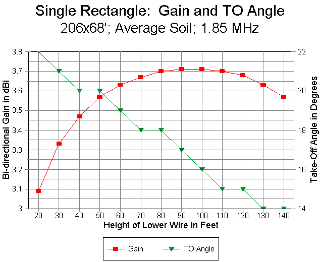
Figure 4 provides modeling data on the single rectangle for bottom wire heights ranging from 20' to 140' up. The antenna top wire will be 68' higher. The left axis records gain over average soil for the various heights. Note that as the bottom wire reaches the 90-100' mark, the gain levels off and then decreases with further increases in antenna height. The second curve referenced to the right axis records the continuous decrease in the elevation angle of maximum radiation, which runs from 23 degrees for the lowest height surveyed to 14 degrees for the highest.
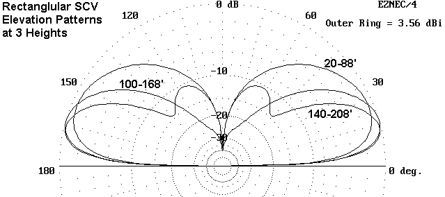
On the very dubious assumption that we have some choice in how high to place the rectangle, we can also use elevation patterns of the antenna as a guide. Figure 5 provides three patterns with the bottom wire at 20' up, 100' up, and 140' up. The decrease in gain with the 140' pattern is already evident, along with the reason for that decrease. Above the height for maximum gain, a secondary lobe begins to appear at a very high angle. With sufficient elevation (above 1/2 wavelength or so), the secondary lobe becomes dominant and the overall low angle gain of the antenna begins to decrease dramatically. However, I doubt anyone will ever test this modeling result by placing the bottom wire of the rectangle above 270' up.
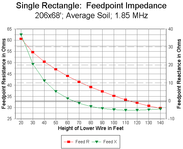
We can see the span of expected feedpoint impedances in Figure 6. At 140' up, the feedpoint impedance approaches that of free space models. The resistive component increases in a regular curve as the antenna is lowered to more usable heights, in accord with reductions in gain as the antenna passes the 90' level on its way down. Also notable as an earth-effect is the increase in inductive reactance with lower heights, a fact suggesting that builders of rectangles at low heights might wish to shrink them to bring them to resonance. (However, before adjusting the antenna size, see the notes on matching below.) Notice that the feedpoint resistance of the antenna at its target frequency (here, 1.85 MHz) is well within the range of direct coaxial cable feed.
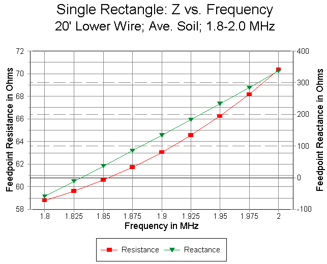
As one might expect, the SWR bandwidth of this antenna, like most 160- meter antennas, is fairly narrow. More important is the information in Figure 7, a track of the resistance and reactance across the band for the antenna when the lower wire is at 20' up. Similar data accrue for higher antenna elevations, but with a shift in the resistance curve according to height.
The range of resistance is rather narrow--under 12 ohms across the band, as read from the left axis. Moreover, the reactance (as read from the right axis) changes in a very linear fashion. It would be simple enough to enlarge the antenna until it displays inductive reactance across the band. A remotely tuned series capacitor might then compensate for the reactance, leaving a resistive impedance suitable for coaxial cable.
160-Meter Single Rectangle Gain and Feedpoint Impedance Over Various Soils

Antenna Height Gain in dBi         Take-Off Angle Feedpoint Impedance
  (in feet)                           (degrees)          (R +/- jX Ohms)

   20-88'
Very Poor Soil    0.34             27             65.1 + 30.0
Poor Soil         1.86             25             62.4 + 34.1
Average           3.09             22             60.6 + 36.8
Very Good         5.24             16             55.7 + 37.4

   60-128'
Very Poor Soil    1.09             23             42.5 -  1.7
Poor Soil         2.55             21             43.1 +  0.2
Average           3.63             19             44.0 +  1.3
Very Good         5.78             14             44.2 +  3.1

  100-168'
Very Poor Soil    1.24             20             33.3 -  5.1
Poor Soil         2.67             18             34.3 -  4.8
Average           3.71             16             35.2 -  4.9
Very Good         6.16             13             36.1 -  4.4


Soil types          Conductivity (S/m)       Dielectric Constant

Very Poor Soil      0.001                     5
Poor Soil           0.002                    13
Average             0.005                    13
Very Good           0.0303                   20

Table 1.  160-meter single rectangle gain, TO angle, and feedpoint
impedance over various soils, with different antenna heights above ground.
The data developed so far has been over average earth, as it is called. Unfortunately, many of use live over earth significantly poorer than average, while a few lucky souls live on very good earth. Table 1 provides some guidance as to expectations for various types of soil ranging from very poor (conductivity (C) = 0.001 S/m; dielectric constant (DC) = 5) to very good earth (C = 0.0303; DC = 20). The figures reflect single side- fed rectangles at base heights of 20, 60 and 100 feet. Similar tables might be drawn up for any vertically polarized antenna and show similar differences from one soil type to the next. However, unlike the delta loops, which showed some aberrant progressions with changes in soil conditions, the course of values shows relative smooth curves from one soil type to the next for rectangles.
The tables are based on uniform soil in every direction from the antenna for distance great enough to fully affect the far field. Of great interest is the lack of significant change in the antenna feedpoint impedance with changes in soil type. It is dubious whether one can effect significant performance improvements in this or any other SCV by doctoring the soil in the immediate vicinity of the antenna. On the other hand, the soil at a distance of 2 wavelengths and more form the antenna is usually beyond control.

The better the distant soil, the better the low angle radiation from the antenna. Figure 8 shows the contrast between very poor and very good soil. Equally important with the gain improvement is the lowered angle of maximum radiation. Were the curves graphically equalized, the higher-angle response would be very little different. However, the low-angle response from the antenna over very good soil is very much enhanced. Intermediate soil types provide intermediate curve shapes.
The sketch shows two significant features. First, the loop must be slightly fatter vertically for maximum gain relative to the single loop. Second, the spacing between the loops has very little effect on antenna gain. In fact, models of the double loop with a space that ranges from 1' up to 12' showed only a 0.01 dB difference in gain.
What did change with changes in spacing was the required total loop size for resonance. The closer the wires, the larger the loop size. Part of this size increase stems from the fact that the crossing wires are longer for wider spacing, thus occasioning smaller outside dimensions. However, the other part is a function of minor interactions between the loops. With a constant length of 206' for the double rectangle array, the loop height was 70' with a 12' spacing and 71' for a 2' spacing.
The remainder of the data was generated on the basis of a 2' space between the wires, simply because that is most likely a more convenient construction distance. Spacers can be almost anything that insulates and is light weight. It is essential that the crossing wires at the far end of the array be well insulated from each other, although spacing appears not to be critical.

The double rectangle exhibits almost a half dB of additional gain beyond that of the single rectangle. Figure 9 shows the gain and take-off angle for lower-wire heights from 20' to 140' up, which permits direct comparison with the corresponding chart for the single rectangle. The curves are highly congruent, with peak gain at about 100' up (with the top wire at 171' up). Since the resolution of take-off angles is one degree, the "stair-step" form of that curve should be no surprise, and 1-degree differences between the graphs for the single and double rectangles are meaningless.
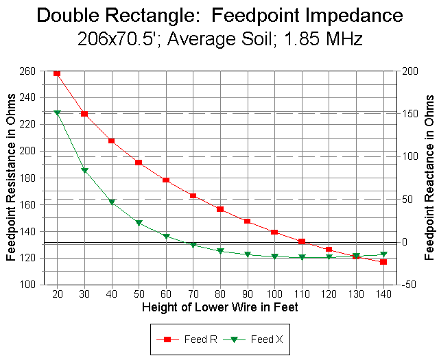
The "transformer" action of the double rectangle configuration appears clearly in Figure 10. The forms of both the resistance and the reactance curves are almost identical to those of the single rectangle, but the double rectangle values are almost exactly 4 times those for the single rectangle. Both resistance and reactance are multiplied.
The curve suggests that almost any parallel feedline might be used to feed the double rectangle. A link-coupled tuner should be able to handle the range of resistance and reactance across 160-meters. In fact, the more typical network tuner with its 4:1 output balun should not be heavily challenged by the impedances presented by the double rectangle.
160-Meter Double Rectangle Gain and Feedpoint Impedance Over Various Soils

Antenna Height Gain in dBi         Take-Off Angle Feedpoint Impedance
  (in feet)                           (degrees)          (R +/- jX Ohms)

  20-91
Very Poor Soil    0.54             27             274 + 120
Poor Soil         2.07             24             264 + 139
Average           3.30             22             258 + 151
Very Good         5.46             16             237 + 156

  60-131
Very Poor Soil    1.38             23             171 -   6
Poor Soil         2.83             21             174 +   2
Average           3.90             19             178 +   7
Very Good         6.06             14             179 +  14

 100-171'
Very Poor Soil    1.60             20             131 -  18
Poor Soil         3.01             18             136 -  17
Average           4.05             16             139 -  17
Very Good         6.50             12             143 -  15


Soil types          Conductivity (S/m)       Dielectric Constant

Very Poor Soil      0.001                     5
Poor Soil           0.002                    13
Average             0.005                    13
Very Good           0.0303                   20

Table 2.  160-meter double rectangle gain, TO angle, and feedpoint
impedance over various soils, with different antenna heights above ground.
Like the single rectangle, soil quality affects the far field pattern fairly strongly without affecting the feedpoint impedance very much. Table 2 presents data for the double rectangle at the same baseline heights as for the single rectangle in Table 1. The increase in gain for the double rectangle is everywhere apparent in the table. However, the chief effect of the table is likely to be to make many folks wish they lived surrounded by very good earth. I did not have the heart to present the salt-water data.
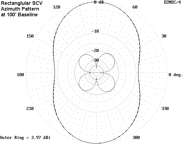
In general, deltas and square loops have more broadly oval patterns with less front-to-side rejection than the rectangle. The half-square pattern is similar to that of the rectangle with a slightly greater front- to-side ratio.
To increase gain further--and in the process double the front-to-side ratio--requires no more altitude, but double the linear space for the antenna. K4VX's open double rectangle with a common center wire or the familiar bobtail curtain provide about 1.5 dB added gain and over 20 dB front-to-side ratio, with comparable take-off angles to the single and double rectangles shown here.4 They are certainly antennas worth investigation if one has a linear space well over 400' long.
These notes are based on computer models of the rectangle, which itself has already been proven in the field. Where computer modeling is at its best is in developing systematic guidance data, and that has been the aim of these notes. Computer models assume level terrain, but the individual contemplating an antenna such as these might well use terrain analysis software by N6BV or K6STI to adjust expectations for the particular antenna site and its environs. The more data we gather in advance, the more realistic will be our expectations for any antenna we might think about building. The 160-meter rectangle makes a good case-in- point.
3.6 MHz Single Rectangle:  Properties Over Average Soil at Various Heights

Soil Type Baseline  Gain      T-O Angle      Feed Impedance
          Height ft dBi        degrees       R +/- jX Ohms


Average    10        2.21            25            50 + 38
(C=0.005,  20        2.76            23            40 + 15
  DC=13)   30        2.98            21            34 +  7
           40        3.08            20            30 +  3
           50        3.11*           18            27 +  2
           60        3.08            17            25 +  2
           70        3.01            16            23 +  2
           80        2.88            15            22 +  3
           90        2.69            14            21 +  4

Note 1.  * = Height of maximum gain
Note 2.  Dimensions of single rectangle = 110' baseline length, 31' height.
          Construction:  #12 AWG copper wire.

Table 3.  3.6 MHz single rectangle:  properties over average soil at
various heights.
With these variations in mind, you can anticipate the values for the 80-meter rectangle that appear in Table 3. Only the values for average soil are shown, since the values for other soils are proportional, using the 160-meter charts as a guide. The height of maximum gain is just about half that for 160 meters. However, over ground, the gain is not as high as the corresponding 160-meter rectangle at twice the height.
Only at low heights is it advisable to feed the 80-meter single rectangle directly with coax. Indeed, the single rectangle above 160 meters is probably a worse choice than its companion double rectangle. Like the 160-meter version of the double rectangle, the 80-meter antenna displays a slight gain over a single rectangle with relative insensitivity to the spacing of the two wires. The sample model placed the wires 1' apart, with the cross-over wires spaced about 0.5' apart. Also like the 160-meter version, the model maintained the same length, but increased the height over the single rectangle by a small amount, ending up with a total height of 32.3' for resonance in free space.
3.6 MHz Double Rectangle:  Properties Over Average Soil at Various Heights

Soil Type Baseline  Gain      T-O Angle      Feed Impedance
          Height ft dBi        degrees       R +/- jX Ohms


Average    10        2.40            25           212 + 132
(C=0.005,  20        2.98            23           164 +  39
  DC=13)   30        3.23            21           138 +   6
           40        3.36            19           120 -   8
           50        3.42            18           107 -  14
           60        3.43*           17            97 -  15
           70        3.37            15            90 -  13
           80        3.26            15            85 -   9
           90        3.08            14            82 -   5

Note 1.  * = Height of maximum gain
Note 2.  Dimensions of double rectangle = 110' baseline length, 32.3'
height.
          Construction:  #12 AWG copper wire.

Table 4.  3.6 MHz double rectangle:  properties over average soil at
various heights.
Table 4 shows the modeled values over average soil at heights ranging from 10 to 90' (with resultant top-wire heights ranging from 42.3' to 122.3'). The added gain over the single rectangle is evident, as is the reduced gain relative to corresponding 160-meter double rectangles. Like the 160-meter models, the height of maximum gain for the double rectangle is slightly and perhaps insignificantly higher than for the single rectangle.
The feedpoint impedance at low heights is likely to benefit from the use of parallel feeders and an antenna tuner. At higher levels, a quarter- wavelength matching section of 75-Ohm cable will provide a 50-Ohm coax match over a small portion of the band. However, the large scale changes in reactance suggest that parallel feeders and a tuner may be best for operation over the entire band.
This basic data, when combined with sensible adjustments to the 160- meter data, should provide reasonable guidance for our expectations should we decide to build one of these antennas. Before we make such a decision, we shall want to compare these data with those in the last episode on deltas. But let's not be too hasty. Final decisions should await a fuller story on the open-ended cousin to these two loops: the half-square.
2. Brian Beezley, K6STI, "A Gain Antenna for 28 MHz," QST (July, 1994), 70.
3. In the HF region, we can use a simpler approximation: (2.8 + 1.4 log F), where F = the frequency in MHz for #12 copper wire. When expressed in terms of natural logarithms, R approaches the Fibonacci constant times ln (100 F).
4. For the open double magnetic slot, see Lew Gordon, K4VX, "The Double
Magnetic Slot Antenna for 80 Meters," The ARRL Antenna Compendium, Vol. 4
(Newington: ARRL, 1995), pp. 18-21.
Updated 5-19-98. © L. B. Cebik, W4RNL. A print version of this note appears in The
National Contest Journal. Data may be used for
personal purposes, but may not be reproduced for publication in print or
any other medium without permission of the author.