 Part 1: The Group Picture
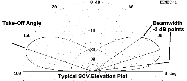
Moreover, these antennas do not need ground planes.
1. All use about 1 wavelength of wire (except for the doubled versions). As with all 1 wavelength antenna systems, the radiation properties can be altered by changing the feedpoint of the system. A 1 wavelength system is not an SCV unless the feedpoint is selected to maximize vertically polarized radiation.
2. SCVs are "closed" systems. A better term might be that they are "complete" systems. They do not require a ground return or ground plane to complete the antenna. Like all vertically polarized antennas near ground relative to the frequency of operation, they do depend to some extent upon the local ground quality for their radiation efficiency. However, they do not depend upon local ground quality for basic operation. Unlike the vertical monopole without its ground plane, the SCVs all model very nicely in free space.
3. SCVs come in several varieties, all of which are related. The two most recognizable shapes are the triangle and the rectangle. Triangles (or "deltas") tend to vary from equilateral to right angle. Rectangles can be anything from squares (quad loops) to long flat rectangles, sometimes dubbed "magnetic slot" antennas.2 Quad loops can be either set up as squares or as diamonds.
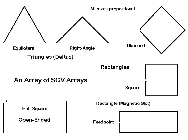
As shown in Figure 2, there is a kissing cousin to these closed loops called the "half square."3 You can in fact trace the evolution from the closed loops to the half square in NEC models. Begin with a triangle fed for maximum vertical radiation. Open the top apex, a voltage maximum, by a very small amount (but not so close at the tips that the program interprets the wires as connected). The properties do not change. The properties evolve as the base wire is extended to a full half wavelength and the open wires are moved to a position at right angles to the base wire.
3. For vertically-polarized operation, all SCVs need to be fed 1/4 wavelength from a high-voltage maximum, in other words, at a current maximum. For the deltas, this position is 1/4 wavelength from the apex. For rectangles, the proper position is mid-side. This position becomes the side peak for the diamond configuration. In free space models of all these configurations, it makes no difference whether the voltage maximum is up or down, since there is no up or down to free space except in conventionalized graphic plots. However, the apex position may make a considerable difference in performance over real ground, while at the same time creating a challenge for antenna support. The advantage of placing the feedpoint as high as possible may conflict with available physical supports for the wire.
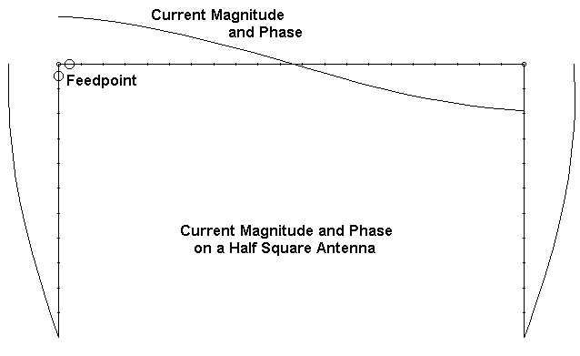
4. The horizontal member that each of these antennas share in common functions largely (but not exclusively) as a 1/2 wavelength phasing line. The high voltage maximum in the center of this line effects a phase reversal for currents, so that they are equal in magnitude but opposite in polarity on either side of the maximum. Hence, the resultant radiation cancels to a high but incomplete degree. The feed point and another point opposite it in the structure are current maxima which are approaching 1/2 wavelength separation and which are phased for additive radiation broadside to the wire assembly. Figure 3 illustrates these features with a half square, whose properties are almost ideal.
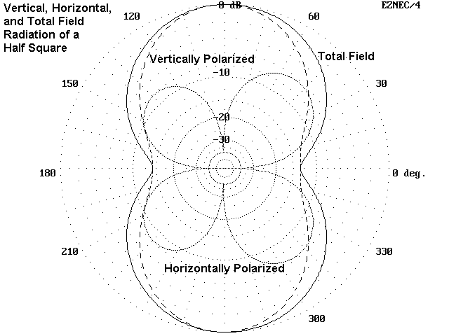
Nonetheless, the resultant radiation pattern is a combination of vertically and horizontally polarized radiation, as illustrated in Figure 4, a typical azimuth pattern for an SCV. This pattern illustrates the degree to which horizontally polarized radiation--either from the "phasing" line or from angled portions of the vertical wires--fails to be cancelled. Although the vertically polarized radiation provides for the antenna's maximum gain, the horizontally polarized radiation increases the beamwidth of this bi-directional array.
For those who like terminological mysteries, the rectangles are symmetrical with respect to top and bottom horizontal wires. Which we should call the phase line and which we should call part of the vertical members of the array is a debate best left to medieval scholastics. In effect, both upper and lower horizontal members perform both functions.
5. All of the SCVs can be arrayed in pairs (or triplets) aligned broadside for either phased or parasitical operation. Therefore, it is possible to create beam arrays, and with some stubs and relays, make the beams switchable in direction. SCVs follow the common parasitical arrangements that require reflectors to be larger than driven elements, which are in turn larger than directors.
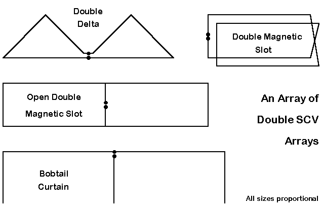
For additional bi-directional gain, SCVs can be placed side-by-side with a common feedpoint. The near-1/2-wavelength spacing of vertical members with the requisite phase reversals along the line(s) yields additive radiation broadside to the array. Hence, there have been open double rectangles, open double deltas, and the bobtail curtain.4 Figure 5 illustrates the shapes of these antennas, along with one other: the double magnetic slot--or double side-fed rectangle. This antenna provides feedpoint impedance transformation from a normally very low value to one more favored by hams.
             Basic Properties and Free-Space Performance of Common SCVs

Antenna Name          Abbreviation 7.15 MHz Dimensions       Free Space      Feedpoint
                                      (in feet)              Gain (dBi)   Impedance(Ohms)

Equilateral Delta         EQD    48.8'/side, base down, apex up   2.9       120

Right-Angle Delta         RAD    60.8' base, 43' sides, base down 3.3        51
                                      apex up

Double Right-Angle Delta  DBD    121.6' base, 43' sides (twice),  5.1        35 (note 1)
                                      base down, apex up

Square Quad Loop          QSQ    36.3'/side                       3.2       130

Diamond Quad Loop         QDI    36.3'/side                       3.1       130

Rectangle (Magnetic Slot) REC    56' horizontal, 12.8' vertical   4.4        15

Double Magnetic Slot      DMS    56' horizontal, 13.0' vertical,  4.7        80 (note 1)
                                      3' separation

Open Double Magnetic Slot ODS    110.8' horizontal, 11.1' vertical; 5.7    30 (note 1, 2)
                                    fed on end wire (center-wire
                                    feed possible)

Half Square               HS     62.4' horizontal, 39' vertical    4.6       65

Bobtail Curtain           BC     125' horizontal, 38' vertical;    6.3     40 (note 1, 3)
                                    fed on center wire

Note 1:  A 2 wavelength system; unmarked antennas are 1 wavelength arrays.

Note 2:  Impedance value for end-wire feed.  Antenna impedance with center-wire feed
is about 9 Ohms.

Note 3:  For center-wire feed of the bobtail, impedance is about 40 Ohms at the
junction with the horizontal wire, about 55 Ohms at 60% up the vertical, and
about 70 Ohms at the middle of the vertical.

Table 1.  Basic properties and free-space performance of common SCVs.
It is clear that the deltas and the squares are very comparable performers, although the right-angle delta (RAD) carries a feedpoint impedance compatible with coaxial cable feedlines. Interestingly, we find also that the rectangle (REC) provides superior gain to the square (QSQ) or diamond (QDI), despite its flattened appearance. However, remember that the sides of the rectangle, where the high current maxima lie, are more nearly 1/2 wavelength apart, providing for better radiation addition. The feedpoint impedance of the single rectangle is, unfortunately, lower than most hams wish to handle. Of the 1 wavelength SCVs, the half square (HS) is the best performer with respect to gain, since its vertical members are a full half-wavelength apart, and the feedpoint impedance is coax- compatible.
Within Table 1, I have added 2 wavelength wire arrays, namely, the double right-angle delta (DBD), the double magnetic slot (DMS), the open double slot (ODS), and the bobtail curtain (BC). Unlike the side-by-side 2 wavelength models, the DMS winds the loops in parallel, with a mobius crossing at the end away from the feedpoint. Not only does the wire doubling in the double magnetic slot increase the feedpoint impedance, but as well, it adds something to the gain. The spacing between the wires is not critical; the model uses a 3' spacing. The open double slot adds more gain with a moderately usable feedpoint impedance (but only if fed on an end wire, since the impedance of the antenna is about 9 Ohms if fed on the center wire).
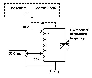
The final gain winner in the group is the bobtail curtain (BC). Fed about midway up the center vertical toward the horizontal wire, the impedance is about 70 Ohms, while at the junction with the horizontal wire, the impedance is closer to 40 Ohms. With patience, a builder can find an exact 50-ohm point between the two. Of course, the free ends of the half- square and the bobtail curtain lend themselves to voltage feed via a simple tapped high-Q parallel tuned circuit, as shown in Figure 6.
                Performance of Common 7.15 MHz SCVs Over Average Ground

Antenna    Height Range  Gain in dBi  Front-to-Side  Take-Off Angle  Feedpoint Impedance
            (in feet)                  Ratio (dB)      (degrees)          (Ohms)

EQD        20 - 62.3      1.5           - 3             18           135 (Note 2)

RAD        19.6 - 50      1.9           - 5             20            60

DBD        19.6 - 50      3.7           -12             20            40

QSQ        20 - 56.3      1.6           - 4             18           145

QDI        20 - 71.4      1.5           - 4             16           135 (Note 2)

REC        37.2 - 50      3.0           -12             17            15

DMS        37.0 - 50      3.3           -12             17            80

ODS        38.9 - 50      4.5           -25             16            30

HS         11.0 - 50      3.4           -15             18            65

BC         12.0 - 50      5.0           -28             18            40 (junction-fed)
                                                                 56 (60% up center wire)
                                                                    70 (mid-center wire)

Note 1:  All antenna #12 copper wire over average earth (conductivity
 = 0.005 S/m; dielectric constant = 13).

Note 2:  This antenna is not physically apt under the terms of the exercise.


Table 2.  Performance of common 7.15 MHz SCVs over average ground.
Table 2 sets out the results in terms of gain, front-to-side ratio, take-off angle, and feedpoint impedance. Technically, the diamond and square quads must be eliminated for violating the upper height limit, along with the equilateral delta. Their numbers are included for reference. The deltas can be operated with their horizontal wires high, for some improvement in performance. Operating the half-square and the bobtail with their horizontal wires low is possible, but at the cost of performance.
The table also provides front-to-side gain ratio numbers that give an indication of the degree of bi-directionalness of the the arrays. The higher gain arrays have higher front-to-side ratios and "peanut" patterns, while the lower gain models tend to have more oval patterns.
In the immediate family of 1 wavelength SCVs, the rectangle and the half square provide the greatest gain. However, the single rectangle has a very low feedpoint impedance, and the double magnetic slot is recommended in its place. The open double slot almost matches the bobtail, and its smaller vertical-plane footprint allows greater height and a lower take-off angle.
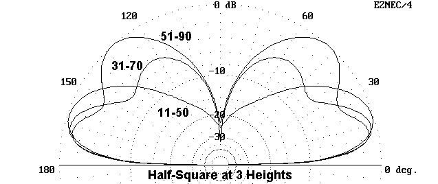
However, none of the SCVs permit unlimited heights without losing much if not all of the low angle radiation advantage. As you elevate any of the SCVs, a second lobe appears at a high angle. Eventually, at a height specific to each antenna type, the higher angle secondary lobe becomes the primary lobe.
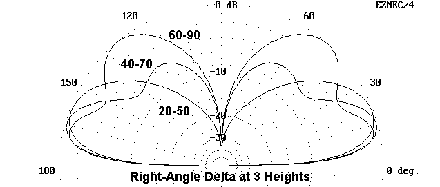
Figure 7 shows the elevation patterns for a 40-meter right angle delta at three heights: with the base at 20, 40, and 60 feet up. Figure 8 shows the same set of elevation patterns for a half square where the lowest heights of the free ends are 11, 31, and 51 feet. The lobe development is virtually indistinguishable between these two antennas (or between any other two of the SCVs).
The entire purpose in using an SCV is to accept the lower gain of the SCV in exchange for the ability of the antenna's vertically polarized pattern to attenuate signals from high elevation angles. The high angle radiation is generally thought to contain most of the non-DX QRM and also the land-mass QRN that makes hearing low-band DX so difficult. The SCVs form a natural filter. Since modern receivers have gain to spare on the low bands, relative to the basic noise level, the lower gain of the SCV is no disadvantage for reception. The low angle of radiation can also be effective when transmitting.
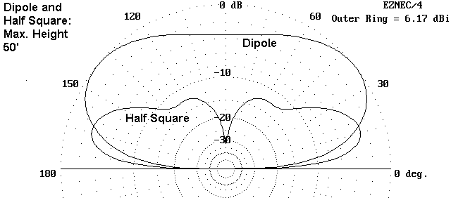
However, if we elevate an SCV too high, it loses its filtering ability without gaining anything significant in low angle radiation. In fact, for raw gain, a simple dipole at the hypothetical exercise height of 50' would do about. Compare the dipole and half square elevation patterns in Figure 9. Note that the half square very low angle radiation exceeds that of the dipole at the same elevation angles, despite the fact that the dipole has an overall gain advantage. One might almost suggest separate antennas for transmitting (the dipole) and receiving (the SCV)--or at least an A-B switch.
1. Although we might simply presume that we can scale the 40-meter results to the other low bands, do the antennas actually perform the same way for each band?
2. The rectangle is a crushed square, and the right angle delta is a crushed equilateral triangle. What are the limits of crushing these geometric shapes before performance deteriorates.?
3. All of the models in this preliminary family reunion have been over uniform average ground (conductivity = 0.005 S/m; dielectric constant = 13). How do the antennas perform over different types of both local and distant ground for each of the three lowest bands?
4. Will any of the changes of soil and shape make any difference in the elevation patterns shapes as they change with antenna height?
We shall look at these questions in future episodes. Since I cannot possibly build and test each type of antenna over all the various soils and in all the various shapes possible, we shall do our exploration by modeling in NEC-4, which is reliable for this class of antennas.5 However, we must note at the outset that antenna modeling provides suggestive results relative to the real world. Because modeling programs presume level ground, they cannot provide detailed information about these antennas on the many sorts of terrain where hams live and use them.
At the same time, our project is just the sort of thing at which antenna modeling excels: the accumulation of systematic data over a wide range of questions. Antenna building must be very selective due to the cost and effort involved and because of the great care that must be used to obtain repeatable and accurate results. For its results to be definitive, the range test must go beyond the anecdotal: all variables must be accounted for in detail to ensure that the results can be formulated as generalizations applicable to other situations that are relevantly similar.
One advantage of modeling in the present case is that each antenna and installation situation can be directly compared with the others, since most of the intervening variables present in real world antennas are equalized in the model set-up. Hence, modeling is a wholly appropriate vehicle for comparing relevantly similar types of antennas--namely, the SCV family.
However, the final choice for an antenna at any site is a mixture of performance potential and physical possibility. If you have only one high support point, then a delta may be necessary, since two-point support antennas are automatically ruled out. If available supports are wide- spread but not exceptionally high, then the rectangles and open-ended arrays jump to the forefront.
Nonetheless, even if your choice is forced by features of the antenna site, learning more about SCVs in general cannot be a bad thing. You never know when someone may ask you a question.
2 For the "magnetic slot" and "double magnetic slot," see Russell E. Prack, K5RP, "Magnetic Radiators--Low Profile Paired Verticals for HF," The ARRL Antenna Compendium, Vol. 2 (Newington: ARRL, 1989), pp. 39-41.
3 The half square antenna actually appeared after its larger sibling, the bobtail curtain. See Ben Vester, K3BC, "The Half Square Antenna," QST (March, 1974), 11-14. Additional notice appeared in Radio Communications for January, 1977 (p. 36). See also Robert Schiers, N0AN, "The Half-Square Antenna," Ham Radio (December, 1981), 48-50. All three of these early sources show the antenna as voltage-fed from one of the free ends.
4 For the bobtail curtain, see Woodrow Smith, W6BCX, "Bet My Money on the Bobtail Beam," CQ (March, 1948), 21-23 and 92-95. See also Smith follow-up articles, "The Bobtail Curtain and Inverted Ground Plane," Parts 1 and 2 in Ham Radio (February, 1983), 82-86, and (March, 1983), 28-30. For the open double magnetic slot, see Lew Gordon, K4VX, "The Double Magnetic Slot Antenna for 80 Meters," The ARRL Antenna Compendium, Vol. 4 (Newington: ARRL, 1995), pp. 18-21.
5 NEC-4 is a proprietary code of the Lawrence Livermore National Laboratory, University of California, from whom a user-license must be obtained. Commercial implementations include the following:
a. EZNEC Pro: Roy Lewallen, W7EL, P.O. Box 6658, Beaverton, OR 97007; e- mail: w7el@teleport.com.
b. GNEC: Nittany Scientific, 1700 Airline Highway, Suite 361, Hollister, CA 95023-5621; sale@nittany-scientific.com.
Because the horizontal baseline of many of these antennas is lower than 0.2
wavelengths, MININEC models of them are less likely to be reliable than
NEC-2 or NEC-4 models.
Updated 4-29-98. © L. B. Cebik, W4RNL. A print version of this note appears in The National Contest Journal. Data may be used for
personal purposes, but may not be reproduced for publication in print or
any other medium without permission of the author.