
 Some Model Quads:
The art of creating a miniature quad--that is, any quad significantly smaller than full size--has been around almost as long as the quad itself. There are many techniques for achieving a smaller size quad. Most fundamental--and perhaps the lossiest--is adding either center or corner inductors to each quad loop.
My own collection of models has focused on a technique that may owe to Paul Carr, N4PC, and which appears in Lew McCoy's book on antennas from CQ Communications. It consists of insetting the loop wires at the low current, high voltage points at the loop sides. Paul reasoned that this form of "linear loading" would have the least impact on gain and front-to-back ratio. I studied variations of the technique, including building some trial versions, for a piece in Communications Quarterly a few years back. The models discussed here will be a selection from the large number accumulated during that study. Like the full-size models we have already examined, all use #14 AWG copper wire. All models will be in free space for consistency with the previous models.
Because the techniques for shortening quad loops are many and varied, this collection of model will necessarily be incomplete. However, the progression of models may provide some background for evaluating other types of miniature quads that you decide to model.
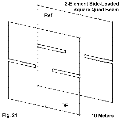
Fig. 21 shows the outlines of a single inset square quad beam. The models we shall look at have 6.96' sides on the driven element. Two versions will be compared, one with 4.31' spacing (0.125 wl), the other with 5' spacing (0.145 wl). The reflector sides are 7.24' and 7.40', respectively.
For those who wish to replicate the models, the following extracts from EZNEC model description files provide the coordinates.
2L 3.46/3.62/4.31 lnld                       Frequency = 28.5  MHz.

Wire Loss: Copper -- Resistivity = 1.74E-08 ohm-m, Rel. Perm. = 1

              --------------- WIRES ---------------

Wire Conn.--- End 1 (x,y,z : ft)  Conn.--- End 2 (x,y,z : ft)  Dia(in) Segs

1  W12E2  -3.460,  0.000, -3.460  W2E1   3.460,  0.000, -3.460    # 14   21
2   W1E2   3.460,  0.000, -3.460  W3E1   3.460,  0.000, -0.125    # 14   10
3   W2E2   3.460,  0.000, -0.125  W4E1   0.825,  0.000, -0.125    # 14   21
4   W3E2   0.825,  0.000, -0.125  W5E1   0.825,  0.000,  0.125    # 14    1
5   W4E2   0.825,  0.000,  0.125  W6E1   3.460,  0.000,  0.125    # 14   21
6   W5E2   3.460,  0.000,  0.125  W7E1   3.460,  0.000,  3.460    # 14   10
7   W6E2   3.460,  0.000,  3.460  W8E1  -3.460,  0.000,  3.460    # 14   21
8   W7E2  -3.460,  0.000,  3.460  W9E1  -3.460,  0.000,  0.125    # 14   10
9   W8E2  -3.460,  0.000,  0.125 W10E1  -0.825,  0.000,  0.125    # 14   21
10  W9E2  -0.825,  0.000,  0.125 W11E1  -0.825,  0.000, -0.125    # 14    1
11 W10E2  -0.825,  0.000, -0.125 W12E1  -3.460,  0.000, -0.125    # 14   21
12 W11E2  -3.460,  0.000, -0.125  W1E1  -3.460,  0.000, -3.460    # 14   10
13 W24E2  -3.620, -4.310, -3.620 W14E1   3.620, -4.310, -3.620    # 14   21
14 W13E2   3.620, -4.310, -3.620 W15E1   3.620, -4.310, -0.125    # 14   10
15 W14E2   3.620, -4.310, -0.125 W16E1   0.930, -4.310, -0.125    # 14   21
16 W15E2   0.930, -4.310, -0.125 W17E1   0.930, -4.310,  0.125    # 14    1
17 W16E2   0.930, -4.310,  0.125 W18E1   3.620, -4.310,  0.125    # 14   21
18 W17E2   3.620, -4.310,  0.125 W19E1   3.620, -4.310,  3.620    # 14   10
19 W18E2   3.620, -4.310,  3.620 W20E1  -3.620, -4.310,  3.620    # 14   21
20 W19E2  -3.620, -4.310,  3.620 W21E1  -3.620, -4.310,  0.125    # 14   10
21 W20E2  -3.620, -4.310,  0.125 W22E1  -0.930, -4.310,  0.125    # 14   21
22 W21E2  -0.930, -4.310,  0.125 W23E1  -0.930, -4.310, -0.125    # 14    1
23 W22E2  -0.930, -4.310, -0.125 W24E1  -3.620, -4.310, -0.125    # 14   21
24 W23E2  -3.620, -4.310, -0.125 W13E1  -3.620, -4.310, -3.620    # 14   10

              -------------- SOURCES --------------

Source    Wire      Wire #/Pct From End 1    Ampl.(V, A)  Phase(Deg.)  Type
          Seg.     Actual      (Specified)

1          11     1 / 50.00   (  1 / 50.00)      1.000       0.000       I

2L 3.46/3.7/5 lnld                           Frequency = 28.5  MHz.

Wire Loss: Copper -- Resistivity = 1.74E-08 ohm-m, Rel. Perm. = 1

              --------------- WIRES ---------------

Wire Conn.--- End 1 (x,y,z : ft)  Conn.--- End 2 (x,y,z : ft)  Dia(in) Segs

1  W12E2  -3.460,  0.000, -3.460  W2E1   3.460,  0.000, -3.460    # 14   21
2   W1E2   3.460,  0.000, -3.460  W3E1   3.460,  0.000, -0.125    # 14   10
3   W2E2   3.460,  0.000, -0.125  W4E1   0.740,  0.000, -0.125    # 14   21
4   W3E2   0.740,  0.000, -0.125  W5E1   0.740,  0.000,  0.125    # 14    1
5   W4E2   0.740,  0.000,  0.125  W6E1   3.460,  0.000,  0.125    # 14   21
6   W5E2   3.460,  0.000,  0.125  W7E1   3.460,  0.000,  3.460    # 14   10
7   W6E2   3.460,  0.000,  3.460  W8E1  -3.460,  0.000,  3.460    # 14   21
8   W7E2  -3.460,  0.000,  3.460  W9E1  -3.460,  0.000,  0.125    # 14   10
9   W8E2  -3.460,  0.000,  0.125 W10E1  -0.740,  0.000,  0.125    # 14   21
10  W9E2  -0.740,  0.000,  0.125 W11E1  -0.740,  0.000, -0.125    # 14    1
11 W10E2  -0.740,  0.000, -0.125 W12E1  -3.460,  0.000, -0.125    # 14   21
12 W11E2  -3.460,  0.000, -0.125  W1E1  -3.460,  0.000, -3.460    # 14   10
13 W24E2  -3.700, -5.000, -3.700 W14E1   3.700, -5.000, -3.700    # 14   21
14 W13E2   3.700, -5.000, -3.700 W15E1   3.700, -5.000, -0.125    # 14   10
15 W14E2   3.700, -5.000, -0.125 W16E1   1.140, -5.000, -0.125    # 14   21
16 W15E2   1.140, -5.000, -0.125 W17E1   1.140, -5.000,  0.125    # 14    1
17 W16E2   1.140, -5.000,  0.125 W18E1   3.700, -5.000,  0.125    # 14   21
18 W17E2   3.700, -5.000,  0.125 W19E1   3.700, -5.000,  3.700    # 14   10
19 W18E2   3.700, -5.000,  3.700 W20E1  -3.700, -5.000,  3.700    # 14   21
20 W19E2  -3.700, -5.000,  3.700 W21E1  -3.700, -5.000,  0.125    # 14   10
21 W20E2  -3.700, -5.000,  0.125 W22E1  -1.140, -5.000,  0.125    # 14   21
22 W21E2  -1.140, -5.000,  0.125 W23E1  -1.140, -5.000, -0.125    # 14    1
23 W22E2  -1.140, -5.000, -0.125 W24E1  -3.700, -5.000, -0.125    # 14   21
24 W23E2  -3.700, -5.000, -0.125 W13E1  -3.700, -5.000, -3.700    # 14   10

              -------------- SOURCES --------------

Source    Wire      Wire #/Pct From End 1    Ampl.(V, A)  Phase(Deg.)  Type
          Seg.     Actual      (Specified)

1          11     1 / 50.00   (  1 / 50.00)      1.000       0.000       I
The length and width of the inset wires can be derived from simple exercises in subtraction. In making the models, I juggled the inset size and reflector loop length for something approaching best performance, although further tweaking of any of the models is certainly possible.
There is a tendency in shrinking quads to shrink the spacing between elements. However, better performance can be obtained with somewhat wider spacing. In these models, 0.125 wl and 0.145 wl spacing are compared. As with past models, 28.5 MHz is the design center frequency for resonance and for maximum 180-degree front-to-back ratio. As we shall see, there are opportunities for sliding either or both of these characteristic to other points within the pass band.

Fig. 22 shows a clear gain advantage for the wider-spaced version of the single-inset square, although the actual amount may not be operationally significant. More notable than this gain differential is the fact that with the shrinking of the quad size, the gain curve is steeper, and the gain peak now falls within the pass band (28 to 29 MHz) rather than below it. At the design center frequency, gain is about 0.5 dB below that of comparable full-size 2-element quad beams.
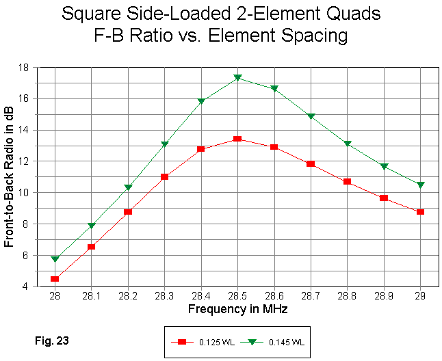
Where the added spacing between elements shows up most graphically is in the front-to-back ratio, as Fig. 23 demonstrates. The wider spaced version not only peaks at a higher value (by about 4 dB), but as well is better across the pass band.
For reference, here are the modeled performance figures for the two antennas at the design frequency.
Antenna        Free Space     Front-to-Back       Feedpoint Impedance
Version        Gain dBi       Ratio dB            R +/- jX Ohms
0.125 wl        6.42           13.4                 76 - j 1
0.145 wl        6.56           17.3                 78 - j 0
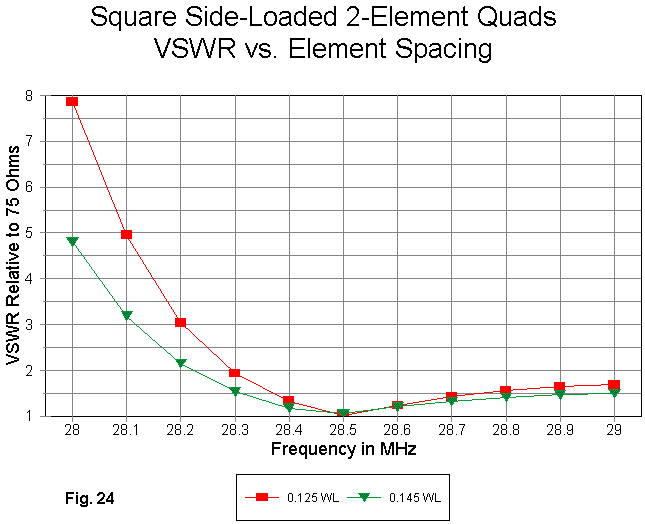
As shown in Fig. 24, wider element spacing also makes the 75-Ohm VSWR curve shallower, especially at the lower end of the band. One aspect of shrinking quads is the fact that it is possible to obtain a low SWR not only at the upper limit of the pass band (29 MHz), but well beyond that point. However, some caution must be used, because the downward curves of both the gain and the front-to-back ratios quickly reduce the antenna performance to just above dipole level.
One can judiciously slide the resonant point of the antenna lower in the pass band by lengthening the driver loop or its insets. Equally judicious sliding of the front-to-back peak by similar adjustments to the reflector is also possible. The latter changes can equalize the front-to-back ratio at the pass band limits. Unlike a full size quad, where the adjustments are fairly (although not completely) independent, changes to one element of the shrunken quad tend to affect the properties normally associated with the other element. Hence, even when modeling, care should be used to make adjustments in small amounts.
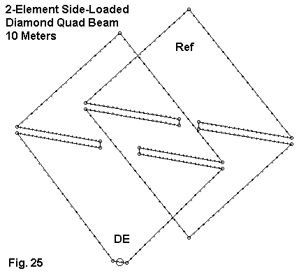
Fig. 25 shows the general scheme of the diamond version of the shrunken quad. The sides are about 6.36' long. For this antenna, the loop dimensions for both the driver and the reflector were held equal, with all adjustments made to the insets. The following model description files provide the coordinates for both 0.125 wl and 0.145 wl versions of the antenna design.
2L dia 6.36/side 4.31 sp lnld                Frequency = 28.5  MHz.

Wire Loss: Copper -- Resistivity = 1.74E-08 ohm-m, Rel. Perm. = 1

             --------------- WIRES ---------------

Wire Conn.--- End 1 (x,y,z : ft)  Conn.--- End 2 (x,y,z : ft)  Dia(in) Segs

1  W11E2   0.300,  0.000, -4.500  W2E1   4.500,  0.000, -0.125    # 14   21
2   W1E2   4.500,  0.000, -0.125  W3E1   0.860,  0.000, -0.125    # 14   21
3   W2E2   0.860,  0.000, -0.125  W4E1   0.860,  0.000,  0.125    # 14    1
4   W3E2   0.860,  0.000,  0.125  W5E1   4.500,  0.000,  0.125    # 14   21
5   W4E2   4.500,  0.000,  0.125  W6E1   0.000,  0.000,  4.500    # 14   21
6   W5E2   0.000,  0.000,  4.500  W7E1  -4.500,  0.000,  0.125    # 14   21
7   W6E2  -4.500,  0.000,  0.125  W8E1  -0.860,  0.000,  0.125    # 14   21
8   W7E2  -0.860,  0.000,  0.125  W9E1  -0.860,  0.000, -0.125    # 14    1
9   W8E2  -0.860,  0.000, -0.125 W10E1  -4.500,  0.000, -0.125    # 14   21
10  W9E2  -4.500,  0.000, -0.125 W11E1  -0.300,  0.000, -4.500    # 14   21
11 W10E2  -0.300,  0.000, -4.500  W1E1   0.300,  0.000, -4.500    # 14    3
12 W21E2   0.000, -4.310, -4.500 W13E1   4.500, -4.310, -0.125    # 14   21
13 W12E2   4.500, -4.310, -0.125 W14E1   0.430, -4.310, -0.125    # 14   21
14 W13E2   0.430, -4.310, -0.125 W15E1   0.430, -4.310,  0.125    # 14    1
15 W14E2   0.430, -4.310,  0.125 W16E1   4.500, -4.310,  0.125    # 14   21
16 W15E2   4.500, -4.310,  0.125 W17E1   0.000, -4.310,  4.500    # 14   21
17 W16E2   0.000, -4.310,  4.500 W18E1  -4.500, -4.310,  0.125    # 14   21
18 W17E2  -4.500, -4.310,  0.125 W19E1  -0.430, -4.310,  0.125    # 14   21
19 W18E2  -0.430, -4.310,  0.125 W20E1  -0.430, -4.310, -0.125    # 14    1
20 W19E2  -0.430, -4.310, -0.125 W21E1  -4.500, -4.310, -0.125    # 14   21
21 W20E2  -4.500, -4.310, -0.125 W12E1   0.000, -4.310, -4.500    # 14   21

             -------------- SOURCES --------------

Source    Wire      Wire #/Pct From End 1    Ampl.(V, A)  Phase(Deg.)  Type
          Seg.     Actual      (Specified)

1           2    11 / 50.00   ( 11 / 50.00)      1.000       0.000       I

2L dia 6.36/side 5.0 sp lnld                 Frequency = 28.5  MHz.

Wire Loss: Copper -- Resistivity = 1.74E-08 ohm-m, Rel. Perm. = 1

              --------------- WIRES ---------------

Wire Conn.--- End 1 (x,y,z : ft)  Conn.--- End 2 (x,y,z : ft)  Dia(in) Segs

1  W11E2   0.300,  0.000, -4.500  W2E1   4.500,  0.000, -0.125    # 14   21
2   W1E2   4.500,  0.000, -0.125  W3E1   0.770,  0.000, -0.125    # 14   21
3   W2E2   0.770,  0.000, -0.125  W4E1   0.770,  0.000,  0.125    # 14    1
4   W3E2   0.770,  0.000,  0.125  W5E1   4.500,  0.000,  0.125    # 14   21
5   W4E2   4.500,  0.000,  0.125  W6E1   0.000,  0.000,  4.500    # 14   21
6   W5E2   0.000,  0.000,  4.500  W7E1  -4.500,  0.000,  0.125    # 14   21
7   W6E2  -4.500,  0.000,  0.125  W8E1  -0.770,  0.000,  0.125    # 14   21
8   W7E2  -0.770,  0.000,  0.125  W9E1  -0.770,  0.000, -0.125    # 14    1
9   W8E2  -0.770,  0.000, -0.125 W10E1  -4.500,  0.000, -0.125    # 14   21
10  W9E2  -4.500,  0.000, -0.125 W11E1  -0.300,  0.000, -4.500    # 14   21
11 W10E2  -0.300,  0.000, -4.500  W1E1   0.300,  0.000, -4.500    # 14    3
12 W21E2   0.000, -5.000, -4.500 W13E1   4.500, -5.000, -0.125    # 14   21
13 W12E2   4.500, -5.000, -0.125 W14E1   0.400, -5.000, -0.125    # 14   21
14 W13E2   0.400, -5.000, -0.125 W15E1   0.400, -5.000,  0.125    # 14    1
15 W14E2   0.400, -5.000,  0.125 W16E1   4.500, -5.000,  0.125    # 14   21
16 W15E2   4.500, -5.000,  0.125 W17E1   0.000, -5.000,  4.500    # 14   21
17 W16E2   0.000, -5.000,  4.500 W18E1  -4.500, -5.000,  0.125    # 14   21
18 W17E2  -4.500, -5.000,  0.125 W19E1  -0.400, -5.000,  0.125    # 14   21
19 W18E2  -0.400, -5.000,  0.125 W20E1  -0.400, -5.000, -0.125    # 14    1
20 W19E2  -0.400, -5.000, -0.125 W21E1  -4.500, -5.000, -0.125    # 14   21
21 W20E2  -4.500, -5.000, -0.125 W12E1   0.000, -5.000, -4.500    # 14   21

             -------------- SOURCES --------------

Source    Wire      Wire #/Pct From End 1    Ampl.(V, A)  Phase(Deg.)  Type
          Seg.     Actual      (Specified)

1           2    11 / 50.00   ( 11 / 50.00)      1.000       0.000       I
For both models, the source is placed on a special wire on the center of its three segments. for reference, here are the design frequency performance figures for the two models:
Antenna        Free Space     Front-to-Back       Feedpoint Impedance
Version        Gain dBi       Ratio dB            R +/- jX Ohms
0.125 wl        6.14           12.6                 82 + j 0
0.145 wl        6.24           16.6                 86 - j 3
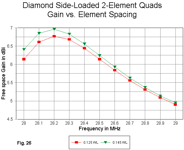
As Fig. 26 shows, the wide spaced version shows a bit more gain than the narrower spaced version. More notable is the fact that the further shrinkage of the design has moved the gain peak farther into the pass band. The lower band edge gain is now significantly lower than the peak gain.
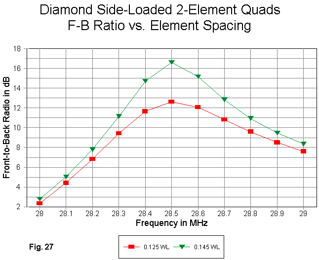
The front-to-back curves in Fig. 27 show about the same differential between versions as those for the 78% square. however, the rate of fall- off from the peak value is much faster. As the size of the quad continues to shrink, it become more important to move the peak front-to-back ratio down the band.
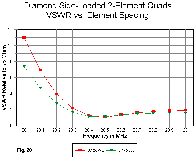
As one might expect, the SWR curves in Fig. 28 are much steeper below the resonant frequency than for the square. Once more, judicious movement of resonance lower in the band can provide a wider operating bandwidth using the usual 2:1 ratio as a guide. Indeed, by appropriate tweaking, one can so position the resonant point and the front-to-back peak to increase the peak value significantly. However, that move must be balanced against the front-to-back performance across the pass band. A sharper peak may not always result in higher values at the pass band edges.

The size of this quad is about 68% of full size, with two equal loops that are 6' on a side. Performance was tweaked by adjusting the length of the insets. The model description provides the coordinates for the two loops and their insets.
2 el square quad, 2 lin load                 Frequency = 28.5  MHz.

Wire Loss: Copper -- Resistivity = 1.74E-08 ohm-m, Rel. Perm. = 1

              --------------- WIRES ---------------

Wire Conn.--- End 1 (x,y,z : ft)  Conn.--- End 2 (x,y,z : ft)  Dia(in) Segs

1  W20E2  -3.000,  0.000, -3.000  W2E1   3.000,  0.000, -3.000    # 14   21
2   W1E2   3.000,  0.000, -3.000  W3E1   3.000,  0.000, -0.375    # 14   10
3   W2E2   3.000,  0.000, -0.375  W4E1   0.580,  0.000, -0.375    # 14   19
4   W3E2   0.580,  0.000, -0.375  W5E1   0.580,  0.000, -0.125    # 14    1
5   W4E2   0.580,  0.000, -0.125  W6E1   3.000,  0.000, -0.125    # 14   19
6   W5E2   3.000,  0.000, -0.125  W7E1   3.000,  0.000,  0.125    # 14    1
7   W6E2   3.000,  0.000,  0.125  W8E1   0.580,  0.000,  0.125    # 14   19
8   W7E2   0.580,  0.000,  0.125  W9E1   0.580,  0.000,  0.375    # 14    1
9   W8E2   0.580,  0.000,  0.375 W10E1   3.000,  0.000,  0.375    # 14   19
10  W9E2   3.000,  0.000,  0.375 W11E1   3.000,  0.000,  3.000    # 14   10
11 W10E2   3.000,  0.000,  3.000 W12E1  -3.000,  0.000,  3.000    # 14   21
12 W11E2  -3.000,  0.000,  3.000 W13E1  -3.000,  0.000,  0.375    # 14   10
13 W12E2  -3.000,  0.000,  0.375 W14E1  -0.580,  0.000,  0.375    # 14   19
14 W13E2  -0.580,  0.000,  0.375 W15E1  -0.580,  0.000,  0.125    # 14    1
15 W14E2  -0.580,  0.000,  0.125 W16E1  -3.000,  0.000,  0.125    # 14   19
16 W15E2  -3.000,  0.000,  0.125 W17E1  -3.000,  0.000, -0.125    # 14    1
17 W16E2  -3.000,  0.000, -0.125 W18E1  -0.580,  0.000, -0.125    # 14   19
18 W17E2  -0.580,  0.000, -0.125 W19E1  -0.580,  0.000, -0.375    # 14    1
19 W18E2  -0.580,  0.000, -0.375 W20E1  -3.000,  0.000, -0.375    # 14   19
20 W19E2  -3.000,  0.000, -0.375  W1E1  -3.000,  0.000, -3.000    # 14   10
21 W40E2  -3.000, -4.310, -3.000 W22E1   3.000, -4.310, -3.000    # 14   21
22 W21E2   3.000, -4.310, -3.000 W23E1   3.000, -4.310, -0.375    # 14   10
23 W22E2   3.000, -4.310, -0.375 W24E1   0.425, -4.310, -0.375    # 14   19
24 W23E2   0.425, -4.310, -0.375 W25E1   0.425, -4.310, -0.125    # 14    1
25 W24E2   0.425, -4.310, -0.125 W26E1   3.000, -4.310, -0.125    # 14   19
26 W25E2   3.000, -4.310, -0.125 W27E1   3.000, -4.310,  0.125    # 14    1
27 W26E2   3.000, -4.310,  0.125 W28E1   0.425, -4.310,  0.125    # 14   19
28 W27E2   0.425, -4.310,  0.125 W29E1   0.425, -4.310,  0.375    # 14    1
29 W28E2   0.425, -4.310,  0.375 W30E1   3.000, -4.310,  0.375    # 14   19
30 W29E2   3.000, -4.310,  0.375 W31E1   3.000, -4.310,  3.000    # 14   10
31 W30E2   3.000, -4.310,  3.000 W32E1  -3.000, -4.310,  3.000    # 14   21
32 W31E2  -3.000, -4.310,  3.000 W33E1  -3.000, -4.310,  0.375    # 14   10
33 W32E2  -3.000, -4.310,  0.375 W34E1  -0.425, -4.310,  0.375    # 14   19
34 W33E2  -0.425, -4.310,  0.375 W35E1  -0.425, -4.310,  0.125    # 14    1
35 W34E2  -0.425, -4.310,  0.125 W36E1  -3.000, -4.310,  0.125    # 14   19
36 W35E2  -3.000, -4.310,  0.125 W37E1  -3.000, -4.310, -0.125    # 14    1
37 W36E2  -3.000, -4.310, -0.125 W38E1  -0.425, -4.310, -0.125    # 14   19
38 W37E2  -0.425, -4.310, -0.125 W39E1  -0.425, -4.310, -0.375    # 14    1
39 W38E2  -0.425, -4.310, -0.375 W40E1  -3.000, -4.310, -0.375    # 14   19
40 W39E2  -3.000, -4.310, -0.375 W21E1  -3.000, -4.310, -3.000    # 14   10

              -------------- SOURCES --------------

Source    Wire      Wire #/Pct From End 1    Ampl.(V, A)  Phase(Deg.)  Type
          Seg.     Actual      (Specified)

1          11     1 / 50.00   (  1 / 50.00)      1.000       0.000       I
The more numerous the insets, the higher the number of wires in a model. For those used to modeling antennas with simple geometries, the model size in terms of both wires and segments may seem high. The relatively thin wire (#14 AWG) allows the use of short segment lengths. For NEC models, the segment junctions should align as closely as possible wherever there are closely spaced wires. This is especially important in the insets.
The following table provides the performance figures at the design frequency for the 68% double-inset square for an element spacing of 0.125 wl. Also in the table are comparative figures for the single-inset diamond and square, using the same element spacing.
Antenna        Free Space     Front-to-Back       Feedpoint Impedance
Version        Gain dBi       Ratio dB            R +/- jX Ohms
68% square      5.87           10.4                 58 - j 0
72% diamond     6.14           12.6                 82 + j 0
78% square      6.42           13.4                 76 - j 1
The following graphs will provide similar comparisons across the pass band.
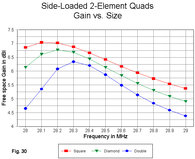
The gain curves in Fig. 30 show hoe the gain peak moves more radically toward the design frequency with each reduction in antenna size. Also worth noting is the steeper rate of gain fall-off in the smaller quads in this collection of models.

When antenna resonance and peak front-to-back ratio are designed for the same frequency, the curves for all three models are exceptionally congruent, as shown in Fig. 31. Note that the front-to-back ratio is almost non-existent at the lower end of the band for the smallest model.

Fig. 32 shows the 75-Ohm SWR curve for the three antennas across the entire first MHz of 10 meters. Besides showing how steep the low end curve is for the 68% square, the graphic actually obscures some interesting properties of the antenna. Therefore, let's eliminate the highest values of SWR.

In Fig. 32A, we obtain a clearer picture of the impedance behavior of the smallest quad, relative to its larger single-inset brethren. The lowest SWR occurs close to 28.6 MHz because the resonant impedance of the antenna is below 60 Ohms. However, note the shape of the curve as it moves toward the upper end of the band. The SWR actually decreases by the time we reach 29 MHz. It would be very easy during antenna adjustment to deceive oneself into thinking that all is well by obtaining a relatively flat SWR curve. However, this curve can obscure the fairly narrow pass band for usable gain and front-to-back ratio.

Fig. 33 shows the general outline of a diamond version of the hat loaded quad beam. Square versions are also easily possible, although the diamond allows the hat wires to be somewhat longer.
A perfect hat would extend outside the loop at the side junction and have two wires exactly end-to-end for relatively perfect radiation cancellation. Placing them inside the loop makes construction easier, since they can be suspended from the normal loop wires. The exact lengths of the wires will vary with their spacing from the loop wires.
For the purposes of comparison, the hat model was made from the 72% diamond, using 5' element separation (0.145 wl). At the original insets, the loop was closed and the hat structure added. The following model description will provide guidance for the coordinates used.
2L dia 6.36/side 5.0 cap load                Frequency = 28.5  MHz.

Wire Loss: Copper -- Resistivity = 1.74E-08 ohm-m, Rel. Perm. = 1

              --------------- WIRES ---------------

Wire Conn.--- End 1 (x,y,z : ft)  Conn.--- End 2 (x,y,z : ft)  Dia(in) Segs

1  W11E2   0.300,  0.000, -4.500  W2E1   4.500,  0.000,  0.000    # 14   21
2   W3E1   4.500,  0.000,  0.000  W6E1   0.000,  0.000,  4.500    # 14   21
3   W1E2   4.500,  0.000,  0.000  W4E1   4.000,  0.000,  0.000    # 14    2
4   W5E1   4.000,  0.000,  0.000         1.589,  0.000,  2.411    # 14   17
5   W3E2   4.000,  0.000,  0.000         1.589,  0.000, -2.411    # 14   17
6   W2E2   0.000,  0.000,  4.500  W7E1  -4.500,  0.000,  0.000    # 14   21
7  W10E1  -4.500,  0.000,  0.000  W8E1  -4.000,  0.000,  0.000    # 14    2
8   W9E1  -4.000,  0.000,  0.000        -1.589,  0.000,  2.411    # 14   17
9   W7E2  -4.000,  0.000,  0.000        -1.589,  0.000, -2.411    # 14   17
10  W6E2  -4.500,  0.000,  0.000 W11E1  -0.300,  0.000, -4.500    # 14   21
11 W10E2  -0.300,  0.000, -4.500  W1E1   0.300,  0.000, -4.500    # 14    3
12 W22E2   0.300, -5.000, -4.500 W13E1   4.500, -5.000,  0.000    # 14   21
13 W14E1   4.500, -5.000,  0.000 W17E1   0.000, -5.000,  4.500    # 14   21
14 W12E2   4.500, -5.000,  0.000 W15E1   4.000, -5.000,  0.000    # 14    2
15 W16E1   4.000, -5.000,  0.000         1.324, -5.000,  2.676    # 14   17
16 W14E2   4.000, -5.000,  0.000         1.324, -5.000, -2.676    # 14   17
17 W13E2   0.000, -5.000,  4.500 W18E1  -4.500, -5.000,  0.000    # 14   21
18 W21E1  -4.500, -5.000,  0.000 W19E1  -4.000, -5.000,  0.000    # 14    2
19 W20E1  -4.000, -5.000,  0.000        -1.324, -5.000,  2.676    # 14   17
20 W18E2  -4.000, -5.000,  0.000        -1.324, -5.000, -2.676    # 14   17
21 W17E2  -4.500, -5.000,  0.000 W22E1  -0.300, -5.000, -4.500    # 14   21
22 W21E2  -0.300, -5.000, -4.500 W12E1   0.300, -5.000, -4.500    # 14    3

             -------------- SOURCES --------------

Source    Wire      Wire #/Pct From End 1    Ampl.(V, A)  Phase(Deg.)  Type
          Seg.     Actual      (Specified)

1           2    11 / 50.00   ( 11 / 50.00)      1.000       0.000       I
The feedpoint is the same as for the single-inset diamond model. For reference, here are the design frequency performance numbers for the two 5'-spaced models.
Antenna        Free Space     Front-to-Back       Feedpoint Impedance
Version        Gain dBi       Ratio dB            R +/- jX Ohms
diamond inset   6.24           16.6                 86 - j 3
diamond hat     6.23           18.4                 93 + j 0

The gain curves in Fig. 34 show a remarkable coincidence, given the physical differences in the load designs. There is nothing to choose in this department.
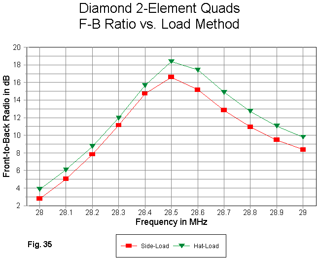
As shown in Fig. 35, the hat model shows about a full dB or slightly greater advantage in front-to-back performance. This amount of added front-to-back ratio would scarcely be noticeable. Moreover, it is not clear that the inset model might not be tweakable to obtain a similar set of values (or the hat model "de-tweaked" by intention or accident to obtain the inset curve).

The SWR curves in Fig. 36 show differences partly as a result of the higher resonant impedance of the hat model. (The resistive portion of the source impedance for all of the antennas we have examined drops to 30 Ohms or less at the lower band edge.) Judicious resonance movement would yield an operating bandwidth that covered most of the first MHz of 10 meters.
Lest we once more fall into the lethargy that equate performance with the SWR curve, let's close with a gallery of azimuth patterns across the pass band for the hatted model. It is an effective compromise between the large and the small square, as well as being virtually identical to the patterns of the 5' spaced inset diamond. Fig. 37 summarizes the performance characteristics of the category of shrunken quads in the versions we have examined here.

Trying to cover all of the varieties of schemes used to miniaturize quad beams would be prohibitive in terms of both time and space. You may add to your collection of shrunken quad models as such models come your way.
The models we have looked at have maintained reasonable efficiency and minimized losses in their means of shrinking the quad. The effects of both loop size and of element spacing have been sampled as a guide to further modeling (not to mention building). My own building of some of them suggests that they will perform to modeled specifications, which provides a useful antenna for limited space.
The one missing feature of these shrunken quads that is prized by many quad users is the ability to nest antennas of this design to produce a multi-band array. Indeed, the full size 2-element quad remains the chief vehicle for this type of service. For the next episode, I shall try to find some of the multi-band 2-element quads hiding in my files. They shall not be hard to find, I suspect. 5-band quad designs, even with only two elements, require large antenna models.
Updated 2-19-99. © L. B. Cebik, W4RNL. Data may be used for personal
purposes, but may not be reproduced for publication in print or any other medium
without permission of the author.