
 Don't Be Phased By Phasing
What Phasing Is: It may be useful to understand a little better what phasing is all about. Any time we have more than a half- wavelength of wire (or more than a quarter wavelength with verticals), we have phasing. Phasing is simply a readout of the current on a designated secondary part of the antenna or antenna system relative to the designated primary part. We are not interested in those currents for their own sake, but for what they do to the resulting radiation pattern of the antenna. The patterns that result are a function of the current magnitudes, the current phases, the length of the primary and secondary parts, and their separation.
Geometric and Electronic Phasing Control: If we understand phasing well enough, we can not only see what the interaction of these 4 phasing factors yields, but we can also control the radiation pattern by juggling the factors. Consider a 2-element Yagi: a driven element and a reflector.
Just the relative lengths of elements and their spacing can determine the current magnitude and phase on the reflector relative to the driven element. There are good combinations and bad combinations--those with more gain and/or front-to-back ratio and those with less. But we quickly learn that with two elements, there is a limit to both gain and front-to-back ratio.
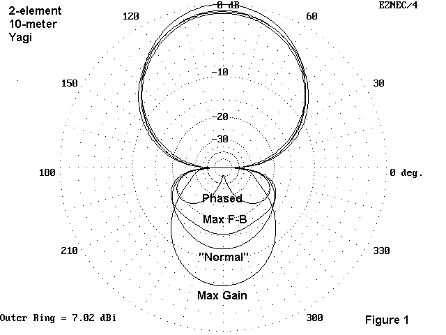
Figure 1 will show some of the limits we encounter, if we supplement it with a small table. The curve marked "normal" is a typical 2-element Yagi design. Let us for the sake of the example freeze a couple of dimensions: spacing is set at 51" and the aluminum elements are 0.75" in diameter. Moreover, in all cases, the current on the front element is given an arbitrary magnitude of 1.0 at 0.00 degrees phase.
Antenna   DE L.     Ref. L.   Gain      F-B       Feed Z    Ref. Current
          inches    inches    FS dBi    dB        R+/-jX    Mag/Phase
Normal    191.0     210.0     6.06      11.0      36+j2     0.64/140.5
Max Gain  191.8     200.0     7.02       5.6      19-j6     0.82/164.1
Max F-B    38.1     204.4     6.22      14.6      0.8-j1100 0.12/145.8
Phased    191.0     210.0     6.35      52.0      -------   0.93/136.4
First, let's explore what some simple changes of geometry can do for and to our antenna. We can alter the lengths of the two elements to achieve the maximum gain from the elements, but at a cost of most of the front-to-back ratio and with a feedpoint impedance that is quite low. To achieve a nearly 5 dB greater front-to-back ratio, we must radically alter the length of the driven element until the feedpoint impedance become wholly unusable. In short, there are limits to what we can achieve simply by altering the physical geometry of the antenna.
Suppose we could control the current magnitude and phase on the rear element without changing the original dimensions of our modest "normal" antenna. One thing we discover is that we cannot squeeze out significantly more gain, but we can improve the front-to-back ratio--at least for a small frequency range. Using the original elements, we find that we can dramatically increase the front-to-back ratio by controlling the current magnitude and phase to the rear element. (The very sharp null in the rear holds good for only a very narrow frequency range.)
One way to achieve the required phasing for a maximum front-to-back ratio is to construct a ZL Special, a 2-element phased array. It uses a precisely calculated set of element lengths, spacings, and an equally precisely calculated length of transmission line between them. The current splits at the feedpoint, part going to the forward element, and part being transformed along the phasing line so that, at the rear element, the current has the magnitude and phase to maximize front-to-back ratio at the target frequency. An alternative is the HB9CV, which aims for a combination of gain (approaching 7 dB) and reasonable front-to-back ratio (about 20 dB) with a specially formulated phase line and matching system. In principle, the HB9CV is a variation of the ZL Special, and both antennas employ the same basic principles.
Of all 2-element configurations that I have encountered, the Moxon rectangle comes closest to achieving the rear element phasing necessary for maximum front-to-back ratio with purely geometric means--that is, without the use of phasing networks or phasing lines. Moxon rectangles are explored in other notes in this collection. Essentially, bending the elements inward toward each other at the ends--in precise lengths and end spacings--alters the element coupling from the standard Yagi straight element design. The cost is a little gain, but the benefit is a highly enhanced front-to-back (and front-to-rear) ratio. The result is also amenable to direct 50-ohm feed and has a very wide operating bandwidth.
Let's look again at the difference between geometric and electronic control of the current on a second element, this time using 1/4 wavelength verticals. We shall set two of verticals exactly 1/4 wavelength apart. First, we shall make both antenna elements the same length and feed only one. That yields the "spaced" pattern in Figure 2. It is a nice pattern, but we can improve the front-to-back ratio. Next, we shall increase the rear (reflector) element length and shorten the driven element back to resonance so that the two elements have about a 4% length difference. The performance peaks out on the curve called "parasitic" in Figure 2. In short, altering geometry can do only so much to establish the conditions for maximum front-to-back ratio. (For many operating situations, the improvement in front-to-back ratio may be sufficient; for others, it will need improvement.)
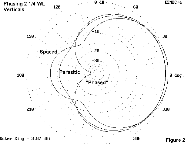
The curve marked "phased" is the pattern of two elements of the same length 1/4 wavelength apart when both are fed in a certain way. The forward element has a current of 1 and a phase angle of zero; the rear element has a current of 1.03 and phase angle of 96 degrees. What the pattern shows is over 42 dB of front-to-back ratio.
The patterns also show other important things. First, the maximum gain set-up differs from the maximum front-to-back set-up. The "spaced" array of two identical elements with only one fed yields the most gain. Both attempts to improve front-to-back ratio show less gain. Second, we always have to evaluate whether the gain or the front-to-back ratio will do us the most good for our operating needs.
More Elements: To improve gain, we shall need more elements, that is, more 1/2 wavelength sections for antenna. Yagis with 3 or more elements alter the relative current phase and magnitude on all unfed elements by the proper spacing and sizing of directors in addition to a reflector. We can also create collinear arrays, that is, antennas with the elements end-to-end. The patterns will add or subtract according to their placement. Think of an extended double Zepp (a 1 1/4 wavelength wire, center-fed) as two half- wavelength wires separated by a quarter wavelength. This spacing lets the dipole patterns add up and narrow for more gain and a narrower beamwidth. The center section establishes the pattern of current distribution along the wire to permit the addition of patterns from the two half-wavelength sections.
Phasing Methods: There are only a few basic methods of altering the current magnitude and phasing of the secondary antenna parts.
1. Element length and spacing: We have seen with both the Yagi and vertical examples how element length and spacing alter current distribution. If we need or want a current distribution that geometry will not give us, then we must use other means.
2. Transmission lines as phasing transformers: Every transmission line is a transformer of voltage, current, and impedance along its length. For antenna work (and contrary to what we think about when considering the feedline to the shack), it is the current phase and magnitude that is most important. How this transformation occurs is a function of the characteristic impedance of the feedline (and its velocity factor). The ZL Special transformation is a very precise thing if one wants more than mediocre results. Not just any line will do, nor will just any length of line (relative to the antenna element lengths and spacing) do. For certain simple cases, like phasing 2 verticals 90 degrees, lengths of line can do the job, but those cases are somewhat limited.
Many collinear arrays make use of phasing lines between element ends. Most are simple cases of reversing the end-to-end phasing. The 1/2 wavelength wire that runs between the two drooping ends of a half-square antenna is such a line. It does not radiate (much), but presents the "far end" vertical with the same magnitude of current as the fed end, but 180 degrees out of phase. The vertical patterns then add to give the peanut- shaped pattern useful to low band DXers. More complex arrays may need precise electrical lengths of phasing lines to effect a specific change of current phase to an adjacent wire, as in collinear EDZs.
3. "Brute force": For precisely tuned phased arrays, nothing beats L- networks (along with PIs and Tees) for establishing the exact phase change needed to make an array work. Every such network changes the phase of the entire voltage-current magnitude set relative to the input (although the voltage and current retain their initial phasing relative to each other). Hence, we can achieve any desired relative current settings. If we then use multiples of a half wavelength of transmission line from the network to the element, we can set each element where we want to set it. Sounds simple, doesn't it.
In some ways it is, but. . .let's not forget that the network also creates an impedance transformation. When we take these matters into account, the calculations can get a little more complex. We have to make certain that the element gets the correct current level and phase under a matched condition. Phasing 3, 4, and more wire systems is an exercise for someone who loves his calculator.
Vertical Phasing: So far we have been thinking in 2-dimensional terms. Now lets add a third--the vertical. We can stack antennas vertically for more gain. The principle is to place the two patterns in a proper phase relationship so that the forward patterns add--a vertical version of collinear pattern adding. The principle works with almost any type of antenna. Vertically spaced EDZs are common. Most vertically spaced arrays feed each antenna in phase--that is, each driven element has the same current magnitude and phase. A number of notes in this collection sample a fair array of different phasing situations.
In another note in this series, we have shown with models that the proper spacing for maximum gain increases for a pair of Yagis increases as the gain of the original Yagis increases. While 5/8 wavelength spacing works well for 3-element Yagis of good gain, we need a lot more space between 5- or 6-element Yagis to get the maximum gain possible from the pair. To make matters a bit hairier, the front-to-back maxima do not occur in the same spacing places as gain maxima. However, the antennas can be redesigned slightly to bring the maximum stacked gain and the maximum stacked front-to-back ratio into alignment.
This small note is not a how-to-do-it manual. We would need a book
for that, and handbooks already abound. Instead, the point is only to
ensure that we understand that phasing is a significant concept even when
there are no phasing networks or phasing lines in sight. If we have
convinced you
that phasing is everything in antenna work, then you may not be phased by
all the references to phasing in what you read about antennas. Phasing can
never be phased out of antenna work.
Updated 2-4-98. © L. B. Cebik, W4RNL. A briefer version of this item appeared in QRP Quarterly, January, 1998. Data may be used for personal purposes, but may not be reproduced for publication in print or any other medium without permission of the author.