MODELING AND UNDERSTANDING SMALL BEAMS
PART 6: FANS, BOWTIES, BUTTERFLIES, AND DRAGONFLIES
Except for the EDZ and the ZL Special, all of the antennas we have look at in this series of small beams have averaged about 3/4ths normal side-to-side length, about 12' on 10 meters. To achieve this size, we had to either adopt a nonlinear geometry (the X-beam and the Moxon rectangle) or load the linear element (the linear-loaded Yagi). The nonlinear geometries were both in the horizontal plane, adding nothing to the height of the antenna structure.
A different alternative, driven by a different goal, is to increase the thickness of the beam's dipoles, thereby automatically shortening them. The goal has been to increase the SWR bandwidth of the basic half-wavelength dipole. A "fat" wire such as a large diameter conduit will achieve this, within the limits of the added weight. However, a virtual fat wire works just as well. A virtual fat wire is a structure of multiple thin wires that simulates by outlining the overall wire size desired. Enter the fan and the bowtie.
The terms "fan" and "bowtie" have a checkered history in amateur antenna lore. Some writers have treated any set of spread multiple dipoles as a fan antenna. The most common use of the term in this way is for 2 or 3 dipoles--with each end independent--cut for various portions of the 3.5 to 4 MHz band. This multiple antenna exhibits separate SWR minima for each dipole. The spread multiple dipole is not what we shall mean by a fan. To be a "true" fan (for our purposes), the structure must electrically connect the element members at the end. The "true" fan is a single virtual fat element that exhibits a single resonant point. Unlike the folded dipole, the wires of each side of the fanned element are also joined that the feedpoint.
Moreover, almost any version of the spread single element (except for the multiwire cage) has been called either a fan or a bowtie, with no distinction between the two terms. Perhaps the use of the antenna in television reception occasioned the double reference, or perhaps it has been around since the antenna achieved some notice in the late 30s and 40s, evolving into the "Wonderbar" of the 50s. However, there are two distinct ways of widening an antenna element. The first way involves a linear fanning of two wires and bringing them back together vertically at the end (with or without a conductive center tube for support): this element we shall call the fan. The second way involves spreading the wires to a maximum separation somewhere along each half of the dipole--usually the midpoint--and bringing them back together angularly toward the end: for obvious visual reasons, we shall call this the bowtie. Fan and bowtie elements have similar, but not identical, properties.
Looking at models of these antenna configurations can lead to the construction of a very practical small beam. Since the center support-conductor of certain fan and bowtie antennas required a large-diameter tube, while the remaining structure was either wire or small tubing, MININEC was the modeling program of choice.1
Center-mounted antennas, like a half wavelength dipole of aluminum tubing, permit simple mountings. Therefore, the classic fat-wire geometry is the fan, as sketched in Fig. 1. Ignoring the horizontal member for a moment, the basic fan consists of a triangular loop of wire or tubing on either side of the center point. Some have been made from a continuous piece of 0.25" to 0.5" diameter tubing, bent to shape, flattened at the center junction, and mounted to a center insulator-support. After a violent thunderstorm, these wind-grabbers often took on shapes only seen in abstract art.
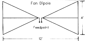
Using a horizontal center support made the structure more durable. Sturdier aluminum tubing of standard Yagi diameters could support a thinner vertical tube at the end. In turn, the vertical tube supported wires forming the slanting members of the fan. The resulting fan slipped the wind well, stressed the tubing for strength, and reduced the element's weight.
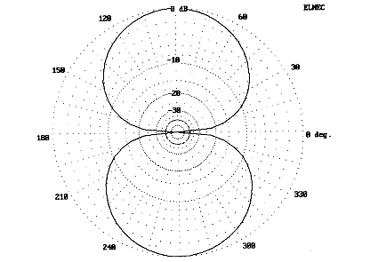
A fan dipole is still a dipole, in fact, a slightly shortened dipole. Therefore, it displays the typical dipole pattern, as shown in Fig. 2, but at with a slight reduction in gain relative to a standard thin-wire dipole. The reduction is insignificantly fractional (about 0.1 dB) and cannot be detected in operation, but it is determinate.2
Adding the conductive center member to the fan structure tends to increase the resonant frequency of a fan dipole relative to a similarly sized fan without the member. The amount of change is not insignificant. A 10-meter fan without the center member with the dimensions shown in Fig. 1 is resonant at about 28.25 MHz, while adding a center member raises the resonant frequency to about 28.75 MHz. The increase in resonant frequency results from changes in the current distribution, some of which is now flowing on the shorter center member. Conversely, fattening the vertical members at the outer ends of each element lowers the resonant frequency.
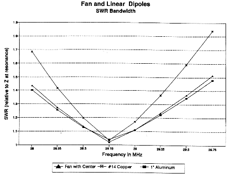
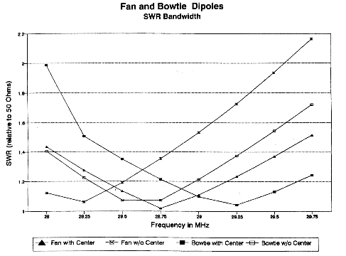
How broad-banded is the fan? The somewhat disillusioning answer appears in the graph in Fig. 3. While the fan with a 3:1 ratio of overall length to vertical height shows an SWR bandwidth that is significantly better than that of a #14 wire dipole, it approximates the bandwidth of a simple horizontal half-wavelength dipole constructed from 1" diameter aluminum tubing. With most rigs, all three antennas would operate satisfactorily across the wide reaches of 10 meters.3 However, the bandwidth advantages of fans will begin to appear when we construct a 2-element Yagi from them.
The fan dipole, using the dimensions of Fig. 1, does have one small additional advantage. The resonant frequency of the structure is close to 50 Ohms, a closer match for the standard ham coaxial feedline than the linear dipole.
An alternative to the fan is the bowtie, another form of the vertically fattened dipole. The bowtie stretches the vertical dimension in the middle of each half of the dipole, as shown in Fig. 4. The vertical supports for the wire perimeter are normally nonconductive. As with the fan, the bowtie may use or omit a conductive horizontal center member.
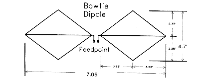
The dimensions shown for the bow tie will produce a resonant dipole at 10 meters. Without a center member, the assembly will resonate at about 28.5 MHz; with the center member, the resonant point moves to 29.25 MHz.
The bowtie shows a resonant feedpoint impedance a bit lower than a fan, but still close to 50 Ohms. Likewise, its SWR bandwidth is quite similar to the fan, as shown in the 4 curves of Fig. 5. Despite the offset in resonant points, the curves are all congruent to a high degree.
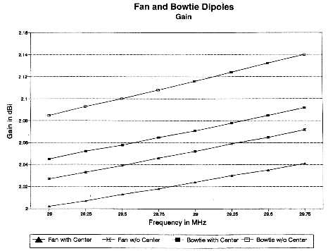
The bowtie requires a larger structure to achieve resonance at the same frequency as a comparable fan, about a foot longer and several inches higher. Largely for that reason, plus the fact that the element is fatter in the region of higher current, the antenna shows a slight gain advantage over the fan (but still marginally less than a linear dipole). However, Fig. 6 demonstrates that the advantage is nowhere greater than 0.1 dB across the band, an increase that could make no difference in practical amateur operation.
Fans and bowties have no magic formulas for determining the ratio of overall length to height. With the exception of the 12' length of the fan, the dimensions are somewhat arbitrary, although the 3:1 length-to-height ratio appears to be a practical limit for home construction. The two antenna configurations do lend themselves to comparisons relative to how fat we make them. The amount of current carried in the fat part of the wire assembly begins to show up in terms of several different factors.
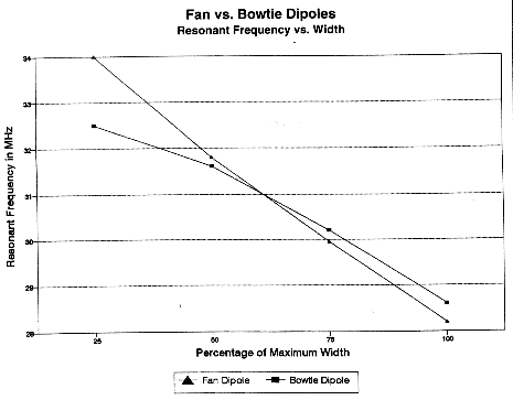
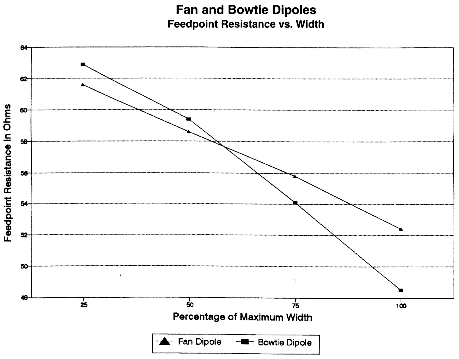
If we reduce the height of the assemblies to 75%, 50%, and 25% of their 10-meter resonant height and then find the resulting resonant frequency, we obtain the two curves in Fig. 7. Note that the curve for the fan dipole is relatively linear, while the curve for the bowtie tapers toward its value for a 7.05' linear element. A similar difference occurs with respect to the gradual increase of the feedpoint impedance as the antenna approaches the condition of being a linear half-wavelength dipole: as shown in Fig. 8, the fan dipole impedance increases almost linearly, while the bowtie impedance tapers toward the dipole value.
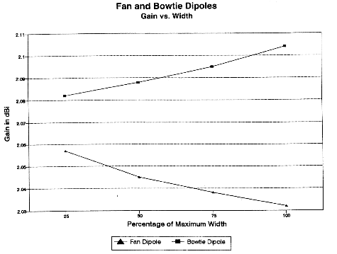
The effects of increasing the height of the bowtie closer to the high-current portion of the antenna structure also show up in a comparison of gain figures. Interestingly, as shown in Fig. 9, the fan's gain increases as it approaches a resonant linear element, but the bowtie's gain decreases under the same condition.
If one wishes to build a half-wavelength dipole to cover all of 10 meters and wishes to have a reasonably good match to 50-Ohm coax, then the fan dipole may be a good choice. Six-foot lengths of aluminum tubing are standard hardware outlet items, and the 4' vertical members may be 0.25" or 0.375" diameter rods from the same source: a single 8' section will suffice for both ends. The wire pieces can be #14 stranded, which is widely available. Construction details will appear later when we look at a practical 10-meter 2-element Yagi.
Since fans and bowties are fat dipoles, rather than loaded or geometrically altered dipoles, we would expect the performance of comparably spaced 2-element Yagis to be similar. For this exercise, we used as a standard the 2-element broadband Orr Yagi, with a driven element 16.1' long, a reflector 17.6' long, and 4.25' element spacing. Centered at 28.5 MHz, this antenna exhibits moderate gain and front-to-back ratio, while holding its characteristics across most of the 10-meter band.
For comparison, we modeled Yagis made up of both fan and bowtie elements. A commercial version of a Yagi using fan elements has enjoyed considerable success: the Butternut HF5B Butterfly beam.4 If a fan Yagi is a butterfly, then perhaps a bowtie Yagi must be a dragonfly.
The bowtie and fan models in this study use 1/8th wavelength spacing. It is easier to retain the basic geometry of the fan and bowtie dipole elements and to load them for parasitic operation than it is to reshape each element for optimal performance without loading. (The Butternut beam also uses this method, since its two basic element structures are identical.) Therefore, the elements in the models have dimensions the same as those in Fig. 1 and Fig. 4. The models explored used horizontal center members, since it is difficult to build a sturdy element without the center tube.
A resonant dragonfly beam requires about 35 load on the reflector for maximum front-to-back ratio. A small inductor or inductive (shorted) transmission line stub across an insulated split in the reflector would provide the required loading.5 The resulting feedpoint impedance at the design center frequency of 28.5 MHz is close to 20 Ohms, with a reactance of +j12. If the inductive reactance is compensated with a pair of series capacitors (about 930 pF each), a 2.5:1 impedance ratio (1.6:1 turns ratio) broadband transformer might provide a good matching system, as would one of W2FMI's baluns. However, one might also consider using a modified beta match, with a capacitor (about 140 pF) across the terminals as the shunt element.6 The actual values requiring compensation may vary with the exact materials used for the elements.
A resonant fan-element Yagi using 12' by 4' with a 1" diameter horizontal center member requires similar treatment. A 1/8th wavelength spaced Yagi using fan elements as described earlier requires reflector loading with either an inductor or a shorted transmission line stub. The driven element shows a resistive feedpoint component of about 17 to 25 Ohms, with an inductive reactive component that varies with the size of the members of the element. One may either use a pair of capacitors on each side of the feedpoint to compensate for the reactance and then insert a 2:1 balun, or one might use a beta match with a capacitor as the parallel element.
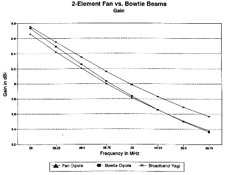
Among the three 2-element Yagi model antennas--the linear, the dragonfly and the fan-element version--there is nothing to choose with respect to pattern, gain, or front-to-back ratio. Fig. 10 records the modeled gains of the antennas across the 10-meter band. The maximum difference of 0.2 dB would be undetectable. The dragonfly and the fan Yagi do exhibit something over 2 dB additional front-to-back gain at design center (as shown in Fig. 11), but this is less than half an S-unit improvement, and that figure deteriorates as one moves to the high end of the band. Moreover, if the reflector is loaded to achieve its gain and front-to-back ratio, the load losses, although quite small, will have an impact on the figures to reduce them very slightly.
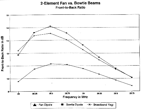
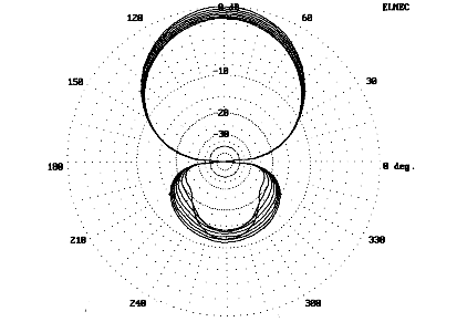
Fig. 12 shows the composite patterns of any of the three antennas across the band. The innermost rear lobe (almost inverted-bell shaped) represents the 28 MHz pattern, as does the highest forward gain circle. The other gain rings decrease sequentially as the frequency increases. Likewise, using an angle of 330 as a reference line, the rear lobe patterns are sequential outward on that line as frequency increases. The innermost lobe line at 270 (directly to the rear of the forward lobe) represents the maximum front-to-back ratio, which is at 28.5 MHz, the design center for all three antennas.
All three antennas have the same gain and front-to-back characteristics. Moreover, the dragonfly and the fan Yagi are more complex structures. Why build anything but a full size Yagi? There are two potential reasons for doing so. First, the full size Yagi is over 17' wide, while the dragonfly is a little over 14' wide and the fan Yagi is 12' wide. If space is at a premium, then fan and bowtie elements may be very useful for giving full-size performance by trading some vertical space for some horizontal space.
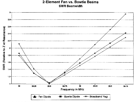
Second, the fan Yagi and the dragonfly have a broader 2:1 SWR bandwidth than a linear 2-element Yagi. Fig. 13 traces those curves. The linear Yagi can cover 28.1 to 29.2 at a 2:1 SWR. However, by moving the design center of the dragonfly and the fan Yagi to about 28.75 MHz, either would likely cover the entire 10-meter band. The fan Yagi is slightly superior in this regard to the dragonfly.
For many--if not most--hams, these reasons may not be significant enough to prompt a construction project. Moreover, the remaining bands from 14 MHz upward are narrower and do not require element fanning for whole band coverage. Nonetheless, it is worth the effort to build a trial antenna to test the values suggested by the models.
Of the two element types--the fan and the bowtie--the fan promises to save the most room with full-size performance. Moreover, it appears easier to build. Therefore, I decided to try a fan-element Yagi, even though I already had a Butternut Butterfly on my tower. The commercial antenna is multiband, has numerous matching pieces attached, and is somewhat larger than the 10-meter model developed here for single-band use. (The Butternut elements are about 12.5' long, with 6' vertical end spreaders on a 6' boom. An individual fan element, minus the added metal of the matching system, is resonant above 25 MHz, with the antenna loaded to Yagi performance on each band.)
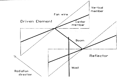
A Yagi using fan dipole elements presents interesting construction challenges. Fig. 14 shows the general outline of a 2-element fan Yagi. Its function is to associate the component names with the physical structures of the antenna. Each element has three major conductive components: the center member, the vertical member, and the fan wire. Everything else, including the boom and mast, are supports. The wire portions of each element come together at the feedpoint or the center of the reflector. The center connection and the boom-to-element support must not interfere with each other. The vertical end pieces must fasten to the center member of the element without slipping. The wires must connect to the vertical member ends with enough stress to stiffen the structure but not enough to deform or break it. A simple system of epoxy-coated plywood plates would not do here.
Since my standard test boom is a 5' length of 1.25" diameter nominal Schedule 40 PVC, I decided to put the drill press to use to mount a 0.5" diameter nominal Schedule 40 PVC through the boom. The real outside diameter of the half-inch material is closer to 0.875" for a good fit with 1" outside diameter aluminum (0.55 thickness) center members, with a little tape at two points on each side of center for a tight fit. If the sag of the Schedule 40 PVC, which allows about a 3-degree droop in the fans, causes concern, you can stiffen the center insulated piece. One technique is to thread thin strips of fiberglass cloth through the center of the half-inch PVC. Then seal one end, stand the piece vertically, and fill it with car-repair epoxy resin. Allow extra setting time, since the tube is closed. The resulting rod is easily machined with wood bits and will outlast any other part of the antenna.
Aluminum rods, either 0.25" or 0.375" in diameter form the end members and fit through holes in the center member. Although I initially had some fears of weakening the center member tubing by drilling out holes, the results has stood the test of time and wind--so far. If you have access to 0.5" diameter aluminum tubing for the end members, you can save a significant bit of downward force at the ends of the center members. The rods used in the test antenna have created no problems and were used owing to their easy access at hardware depots.
Actual construction may take any electrically and mechanically sound form. The construction method used in the test antenna began with a 5' length of 1.25" (nominal) Schedule 40 PVC. At a distance of 4.31' apart, I used a 7/8" diameter hole cutter (for wood) to form the openings for the center-member supports, two 3' lengths of 0.5" (nominal) Schedule 40 PVC. Aligning the first hole for the center of the tubing in a drill press or other jig is the first careful task. A little sanding prepares the opening for the center member support, which is bolted in place with a 2" long #10 stainless steel (SS) bolt and nut. The first support acts as an alignment tool for setting up the second hole in the boom. The half-element fans will slide over the center-member support during final assembly, as shown in Fig. 15. For now, remove the supports from the boom.
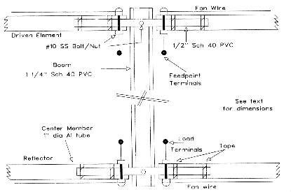
To prepare the 1" diameter 6' long aluminum center members, use a drill press or other alignment jig to drill 0.25" (or 0.375" for 3/8" rod) holes within a half inch of the outer end of each tube. Slide the 4' sections of aluminum rod through the holes with their centers in the middle of the tubes. Several clamping systems are possible. The simplest might be a pair of the smallest size stainless steel hose clamps available placed above and below the center member. A #6 or #8 SS bolt and nut assembly can act as an electrical contact to a small flat spot filed on the rod. Alternatively, the U clamp shown in Fig. 16 can be inserted while passing the rod through the tube. The U should be just large enough to press into the tube. Again, a separate bolt and nut system should be used to ensure good electrical contact between the two elements.

Drill a hole in each end of each vertical member for a bolt and nut to secure a clamp to be soldered to the fan wire, as suggested in Fig. 16. The sketch shows separate wire clamp and wire elements, but wrapping the wire around the nut and using a sufficiently large washer to provide good electrical and mechanical contact should also suffice. Wrap the wire back around itself for mechanical strain relief and solder the wire with a large iron or small torch. (Be certain that the #14 fan wire is long enough--about 12.65' plus wrap-around stubs--to make both fan wires on each side from one wire length. See below.)
Prepare the hole in the center member at the antenna element center. At this stage, it is easiest to insert the PVC center-element support to ensure total system alignment. If the fit is too loose, wrap electrical tape around the support at a minimum of two points to create a snug but nonbinding fit. If you fit both halves of the element to the support and lay them on a floor surface, you can assure your self that the fan wire bolt holes at the center (see Fig. 15) will be aligned.
The bolts closest to the boom that secure the center member to the PVC support should be about 2" long, since they will go through the center member and support, secure the feed and loading elements, and clamp the fan wire. Extra nuts and washers are useful to isolate these functions. You can place the fan wire on the "outside" of the overall structure, using large washers to clamp the midpoint of the wire and secure the assembly (to this point, without matching or loading elements) with a lockwasher and nut. Later, you can add leads for the antenna feed and for the reflector load.
The fan wire for each half element can be a continuous piece running from the upper tip of a vertical member to its lower tip (12.65' plus stubs). Prepare one tip-end as earlier described and run the wire around the bolt at the center. Stress the vertical member slightly and clamp the center bolt. Then run the wire to the other tip, choosing a length that will stress that end of the rod by an equal amount. Now you can cut and finish the wire according to your choice of tip clamps. Finally, loosen the clamping washers and nut at the element center. Equalized the stress on the vertical member and reclamp.
While the element is flat on the floor, you may add a second bolt through the center member and its support near the end of the support within the tube, about 15 to 17" from the element center. Choose a point that does not go through the tape shim.
Once both antenna elements are ready, insert the center-member support PVC through the boom hole and lock it in place with its bolt. (The boom will likely be vertical if the antenna element is on the floor during this phase of assembly. I taped mine to a plumb house support post to assure correct element alignment during this step of construction.) Reassemble the other half element to the support, remembering to clamp the fan wire center with equal stress on the vertical member tips. Using a prop to support the completed element, add the second element to complete the basic assembly. Place a boom-to-mast plate at the center of the boom and install a short section of mast. These additions will permit you to balance the assembly in a fixture while installing the feedpoint match components and the reflector load. I use an old "dish-pack" box with a 1.25" hole in the top as my favorite prop for light antennas.
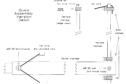
After experimenting with several construction techniques for long-term installation, the final test antenna opted for the most rapid assembly and disassembly techniques. Fig. 17 shows some of the variant details of this option. Vertical members were locked in place with stainless steel hose clamps. The wires passed over grooves in the ends of the vertical rods and were clamped with similar hose camps. The resultant structure requires about 15 minutes for field assembly and a like time for disassembly. The antenna pieces and the 4 sections of 5' 1.25" diameter masting require a space about 1' by 1' by 6' in the back of a pickup truck for transport.
The antenna is almost ready for testing. The study of the general properties of fan and bowtie elements and their Yagi counterparts employed simplified models using #14 copper wire for all members. The trends and curves that result from these models are accurate, but changes in materials will alter the test results and expectations of performance, especially with respect to matching and feeding the array. The actual antenna is predominantly aluminum, and element sizes are variable, with #14 wire, 0.375" diameter vertical members, and 1" diameter center members. Therefore, the antenna was remodeled using these figures to ascertain how close to reality the model would be. Additionally, the model was run at a height of 20' above real medium earth, as MININEC defines it (remembering that MININEC calculates feedpoint impedances as if over perfect ground).
A detailed model of a single fan element dipole showed resonance at about 28.7 MHz, with a feedpoint impedance near 50 Ohms. Raising the antenna assembly with only the driven element mounted on the boom, I found a resonance closer to 28.5 MHz. The differences stem partly from limitations of the modeling program, since very small corners of the fans are cut off, despite extensive element tapering. The greatest part of the variance stems from the inevitable differences between the model and the constructed element. The 1.75" diameter boom adds that much to the overall element length, minus part of the 0.5" inset at the ends for the vertical members. Additionally, the vertical members are stressed, creating slight bows rather than truly straight vertical members.
Remodeling the Yagi version of the antenna suggested reflector loading of about 18 for maximum front-to-back ratio, which translates into a 0.5" inside diameter coil with 3 turns space to just under a half inch in length. Alternatively, a 2.5" wide stub between 3" and 4" long, with a shorting bar, matched the terminal spacing of the reflector element of the test antenna. (See the appendix for a utility program for calculating stubs.) The revised model also reported a feedpoint impedance of about 26 + j24 , values close to optimum for a beta match with a capacitor of about 110 pF as the parallel reactance. Both the reflector coil and beta-match capacitor would be subject to experimental variation to see how close to reality the model came.
As with most Yagis, the fan-element beam can be initially tuned near the ground by pointing it as straight up as possible, with the reflector toward the ground.7 Adjusting the reflector load for minimum SWR should place the antenna at its maximum front-to-back ratio operating point. The predicted beta-match capacitor--110 pF--can be varied to further reduce the SWR. The value may be less than predicted if the series inductance in the driven element is less than 25 Ohms.
Tune-up of the test antenna began with a 2.5" wide stub a bit over 4" long, with a shorting bar and a 100 pF beta-match capacitor. Reducing the stub to almost exactly 4" and reducing the capacitor to 75 pF produced a broad 2:1 SWR bandwidth between 28 and 30 MHz, with lowest readings (1.1:1) for 100 kHz around 28.75 MHz. Part of the below-predicted capacitance for the beta match stems from stray capacitance across the feedpoint assembly, part from a deficit of inductive reactance in the driven element as the frequency was lowered. At a 20-foot height, the best stub length was 3.5" with the same beta-match capacitor, and the region of lowest SWR was narrower. In addition, the center frequency shifted upward by 250 kHz. Although a coil across the reflector produced similar feedpoint readings, the stub proved more rugged and simple and is recommended for similar antennas.
Because the driven element's inductive reactance is marginal for a beta match at the lower end of 10 meters, the SWR curve is much steeper at those frequencies than the curves graphed in Fig. 13. There are at least two solutions to this problem. One is to use a different matching system. Another is to enlarge the elements by a couple of inches, either horizontally or vertically, in order to lower slightly their natural resonant points in the Yagi configuration. This latter measure would also reduce the amount of reflector loading required.
One interesting characteristic of the fan-element Yagi is its apparent greater susceptibility to coupling effects from surround objects than other linear antennas tested at precisely the same location. SWR variations as the antenna was rotated were greater than those experienced with any other test antenna. Since the antenna is not a closed loop (as is the quad), but instead a pair of dipoles with broad vertical end surfaces, its tendency toward unwanted end coupling is no surprise. A fan-element beam should be used in as clear an area as possible.
Operationally, the antenna appears to be a typical 2-element beam, similar in gain and front-to-back ratio as any other. It remains reasonably matched as one moves up 10 meters well past the point where gain and front-to-back ratio have diminished noticeably. In short, the fan-element beam behaves close to the predictions of the model, despite limitations on exact correspondence imposed by both MININEC constraints and construction deviance. Indeed, without a computer model with which to begin, I would not have known just where to begin the process of shortening the elements as I spread their ends. The ham antenna builder does not require lab-grade predictions, but reasonable expectations for construction and testing.
A fan-element Yagi may be the most practical way to obtain full 2-element Yagi gain from a 12'-wide antenna without sacrificing SWR bandwidth. In fact, the bandwidth is improved, which is a plus for a band as wide as 10 meters. The 2-S-unit front-to-back ratio does not equal that of the narrower-bandwidth linear-loaded Yagi or the superb figure of the Moxon rectangle, both comparably sized antennas. However, as has been noted along the way, the final selection of antenna features and specifications requires attention to the major operating goals for a given station. For some operators, a high front-to-back ratio is the key element to success (if the gain among eligible antennas varies by only a dB or so), while for others, excessive front-to-back ratio can actually hinder operations.
The fan-element Yagi has its best home on 10-meters (and perhaps on 6 and 2, for some styles of operating). The smaller frequency range of the lower bands from 20 through 12 meters permits successful use of linear elements, even linear-loaded elements, with their simplified construction. However, for 10-meter operators whose interests require spanning the band from end-to-end, fan elements are worth serious consideration.
The vertical dimension of the fan-element Yagi, especially the commercial Butternut HF5B Butterfly, approaches that of a small quad. A 2-element quad has the further space-saving benefit of reducing the horizontal dimension to about half that of a linear Yagi. Some experimenters have tried to reduce the quad dimensions even further. This series would be incomplete if we did not take a good look next time at shrunken quads.
1. NEC-2, while having advantages over MININEC in many respects, has difficulty in dealing with complex geometries involving wires of significantly different diameters. The models of fans, bowties, and their 2-element Yagi counterparts do not tax the limits of MININEC. All patterns and figures graphed were derived from ELNEC 3.02. Initial models used all #14 wire, while subsequent models, especially of antennas based on the fan, replaced the center member with a 1" diameter tube in order to model the practical antenna actually built. Because the antenna elements have many right and acute angles, elements were extensively segment-tapered. The resulting Yagi models required 198 segments for fan versions and 190 segments for bowtie versions.
2. I have discovered that some hams believe that a half wavelength dipole shows maximum gain at its resonant frequency. This belief likely represents a confusion between the gain of the main lobe and our ability to get the antenna to perform due to the increasing SWR off its resonant frequency. The bidirectional lobes of a dipole show reduced gain (in dBi) as they are shortened below resonance at a frequency of interest and more gain as they are lengthened. The gain increases with wire length until the antenna is about 1.25 wavelengths long (the EDZ), after which the main pattern lobes begin to decrease as the formerly minor lobes increase.
3. For this reason, fans have not found widespread use on the lower bands. On 80 meters, a better choice may be dual dipoles, one cut for the CW end of the band, the other for the phone end. The dipoles may be connected at the feedpoint or you can use close-coupled spacing for similar broadband results.
4. Although not an insignificant task to assemble and tune, the HF5B performs to specifications supplied by the maker. My 12-year-old model has survived a local area house move (thanks to a very careful mover) and continues to perform as specified. Although its dimensions are a bit larger than the fan Yagi given here in order to accommodate multiband operation, the principles remain the same. Butternut records in their instruction manual that "BUTTERFLY" is a trademark, although the status of the lower-case version of the word is uncertain. (In any event, we shall not have to revert to the original term "flutterby" when referring to certain showy insects.)
5. See the Appendix for a short utility program to calculate transmission line stubs from required capacitive or inductive reactances. The program also permits use of capacitor or inductor value inputs and allows for commercial or home-constructed transmission lines.
6. See Thomas Cefalo, Jr., WA1SPI, "The Hairpin Match: A Review," Communications Quarterly, Summer, 1994, pp. 49-54; L. B. Cebik, W4RNL, "Technical Conversations: Further Notes on the Beta Match," Communications Quarterly, Winter, 1995, pp. 51-54; Gooch, Gardiner, and Roberts, "The Hairpin Match," QST (April, 1962), 11-14, 146, 156; and Jerry Hall, K1TD, ed., The ARRL Antenna Book, 16th Ed., pp. 26-21-26-23.
7. See Brian Beezley, W6STI, "Adjusting HF Yagi Matches." "Technical Correspondence," QST, April, 1995, p. 74.
Inductive (shorted) and capacitive (open) transmission line stubs less than 1/4 wavelength long are very useful for introducing frequency-sensitive amounts of inductance (or inductive reactance) or capacitance (or capacitive reactance) into circuits. Their main use is in antenna work, where they serve to load antenna elements (electrically lengthen or shorten them). They also serve as inductors or capacitors in matching networks.
The simple GW Basic utility program that follows allows you to calculate the length of either an inductive (shorted) or capacitive (open) stub by entering the frequency of interest and either a reactance value or a capacitance or inductance. Then you may enter either the known line impedance (Zo) or the physical dimensions (wire size and spacing in inches) of a feedline (along with its velocity factor). The program will then provide the stub length. The program likely replicates similar utilities written by large numbers of folks, but since I found none among my freeware stock, I wrote this one. I list it on the assumption that some few others might also need such a program. A visually enhanced version of the program appears in the latest version of HAMCALC by George Murphy, VE3ERP.1
Even number wire sizes that are greater than 3 and less than 19 (for example, 10, 14, 18) will be automatically recognized as AWG sizes. Decimals (e.g., .25) and whole numbers less than 3 are wire diameters in inches.
For somewhat greater accuracy, especially with large wires and close spacing, substitute the following for line 250:
250 SD=SP/DIA:ZO=120*LOG(SD+SQR((SD*SD)-1))
The chief error trapping is for division by zero whenever a potential denominator is accidentally entered as a zero. An arbitrary minuscule number substitution avoids the program break, but the results will be meaningless, and a retry is necessary.
10 'file XMSNSTUB.BAS
20 CLS:COLOR 11,1,3
30 CLS:PRINT"Calculation of Inductive and Capacitive Stubs":PRINT"L. B. Cebik, W4RNL"
40 PRINT:PRINT"For any value of Lx, Cx, L, or C, calculates the length of a transmission line stub for a given frequency."
50 PRINT:INPUT " Enter frequency of interest in MHz",F:FB=F*(1000000!)
60 PRINT:PRINT" Select desired starting point:":PRINT"A. Inductive Reactance B. Capacitive Reactance":PRINT"C. Inductance D. Capacitance"
70 PI=3.141592654#:T=0
80 A$=INKEY$:IF A$="A" OR A$="a" THEN 110 ELSE IF A$="C" OR A$="c" THEN 90 ELSE IF A$="B" OR A$="b" THEN 140 ELSE IF A$="D" OR A$="d" THEN 120 ELSE 80
90 'Inductance to inductive reactance
100 INPUT" Enter Inductance in microHenries",L:LB=L*.000001: LX=((2*PI)*(FB*LB)): T=1:GOTO 150
110 INPUT" Enter Inductive reactance in ohms",LX:T=1:GOTO 150
120 'Capacitance to capacitive reactance
130 INPUT" Enter Capacitance in picoFarads",C:CB=C*(1E-12):CX=1/((2*PI)*(FB*CB)): T=0:GOTO 150
140 INPUT" Enter Capacitive reactance in ohms",CX:T=0:GOTO 150
150 'Stub construction
160 PRINT:PRINT" Select desired starting point for stub construction":PRINT"1. Feedline Zo 2. Line structure"
170 B$=INKEY$:IF B$="1" THEN 180 ELSE IF B$="2" THEN 200 ELSE 170
180 INPUT" Enter Zo of transmission line",ZO
190 INPUT" Enter Velocity Factor of transmission line",VF:IF T>0 THEN 280 ELSE 370
200 INPUT" Enter Line spacing in inches",SP
210 INPUT" Enter Wire diameter in inches or in even AWG",DIA
220 IF DIA>3 THEN IF DIA=4 THEN DIA=.257 ELSE IF DIA=6 THEN DIA=.186 ELSE IF DIA=8 THEN DIA=.144 ELSE IF DIA=10 THEN DIA=.1019 ELSE IF DIA=12 THEN DIA=.0808 ELSE IF DIA=14 THEN DIA=.0641 ELSE IF DIA=16 THEN DIA=.0508 ELSE IF DIA=18 THEN DIA=.0403
230 IF DIA>3 THEN 210
240 IF DIA=0 THEN DIA=.0000001
250 ZO=(276*.43429)*(LOG((2*SP)/DIA))
260 INPUT" Enter Velocity Factor of transmission line",VF
270 IF T>0 THEN 280 ELSE 370
280 'Inductive stub
290 PRINT:PRINT" Inductive stub for a reactance of";LX;"ohms and a Zo of";ZO;"ohms"
300 IF ZO=0 THEN ZO=.0000001
310 LR=ATN(LX/ZO):LDG=(180*LR)/PI
320 IF F=0 THEN F=.0000001
330 LFT=(VF*LDG)/(.366*F)
340 PRINT"Length of Inductive stub =";LFT;"feet"
350 PRINT:PRINT" <A>nother run or <Q>uit?
360 C$=INKEY$:IF C$="A" OR C$="a" THEN 30 ELSE IF C$="Q" OR C$="q" THEN END ELSE 360
370 'Capacitive stub
380 PRINT:PRINT" Capacitive stub for a reactance of";CX;"ohms and a Zo of";ZO;"ohms"
390 IF CX=0 THEN CX=.0000001
400 LR=ATN(ZO/CX):LDG=(180*LR)/PI
410 LFT=(VF*LDG)/(.366*F)
420 PRINT"Length of Capacitive stub =";LFT;"feet"
430 PRINT:PRINT" <A>nother run or <Q>uit?
440 C$=INKEY$:IF C$="A" OR C$="a" THEN 30 ELSE IF C$="Q" OR C$="q" THEN END ELSE 440
1. HAMCALC (Version 38 as of this writing, but undoubtedly higher by now) is available from VE3ERP, 77 McKenzie Street, Orillia, Ontario L3V 6A6. Murph requests a $5 donation to cover disks, mailers, and postage, and he donates the excess of donations over costs to a Canadian institute for the blind which offers amateur radio services. The program includes a structured menu system, its own copy of GW Basic, and nearly 100 handy calculation programs of interest to hams. They range from basic ohms law computations to more complex antenna, transmission line, inductor, and basic matching system calculations, with tables of wire, cable, and other construction materials, as well as many more features.