 Short Beams and Operating Bandwidth
Actually, the SWR measurements are made in many places: at the antenna feedpoint, at the coax-to-antenna network input terminals, and even at some prescribed length of some prescribed type of coaxial cable connected to the matching network and the antenna. However, for our purposes, the 2:1 SWR figure may be references to the antenna's resonant impedance on the premise that a matching network will transform that impedance to 50 ohms resistive.
So our question is this: how do we get decent operating bandwidth from a half size Yagi? Understanding a few of the principles involved may also assist the average ham to understand a little the problems of antenna design that require careful engineering by manufacturers.
Consider full size dipoles. Let's compare three dipoles at a height of 70' above average ground. In fact, all of the antenna models we explore here will be set 70' above average ground so that the results will be directly comparable. Besides, 70' is just about a half wavelength at 7.15 MHz, our design target frequency.
Let's use #12 copper wire for one of them, a most common choice. The antenna will be 67.3' long, at least in the model. Let's also use 0.5" and 1.0" aluminum tubing. for antennas that are 66.9' and 66.6' long, respectively. As we all know, the fatter the antenna wire, the shorter the antenna at resonance.
However, within limits, fattening the wire also raises the antenna gain a bit. Not by enough to make an operational difference, but at least in a mathematically significant way. The chart of dipole gains for the three antennas from 7.0 to 7.3 MHz clearly shows the differences.

Newcomers are sometimes surprised to see the gain increase as the frequency increases. As frequency increases, the antenna become longer relative to a resonant half wavelength, and a longer antenna means higher far field gain. In fact, the gain increase steadily (at the cost of beamwidth) until the length of the antenna exceeds 1.25 wavelengths. Somewhere between this point and about 1.5 wavelengths, the main lobes begin to split, and each lobe shrinks a bit for a while.
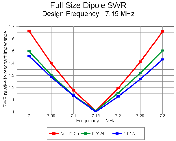
However, our interest in dipoles is for the sake of their use in Yagis, so lengths near to a half wavelength will be our focus. Not only does the gain go up as the wire gets fatter, but as well, the operating bandwidth gets wider. As the next graph shows, all three antennas will show under 2:1 SWR across 40 meters, but the fatter models show a much slower increase in SWR as we move away from the design center frequency.
What happens to this operating bandwidth if we shorten and load the dipole. Since the most common form of loading used in 40-meter antenna design is mid-element loading, we shall follow that lead. Second, because the most common element length used in common 40-meter beams is about half size, we shall set 36' (432") as our general target.
Since we are not actually designing a real beam, but only trying to see some of the principles involved, we shall arbitrarily freeze one variable: element diameter. We shall use 1" aluminum tubing throughout. We should understand that the actual lengths used by manufacturers may depart from 36' by virtue of choosing not just a different element diameter, but as well a tapering schedule. A tapering schedule is simply a fancy name for the progression of smaller tube section diameters, working from the boom outward.
Working with a 36' section of 1" diameter aluminum tubing, we next set inductive loads about halfway between the boom and the element ends. The required inductive reactance needed to resonate the 36' piece of aluminum at 7.15 MHz is 511 ohms per load. This value works out to be 11.375 microH at the design frequency. (If we are to run reasonably accurate frequency sweeps across 40 meters, we must ultimately enter the load into the modeling program as an inductance--with a series resistance for Qs less than infinity.)
Before we look at Q, let's first see what we might use to make the inductive load. First is a coil with the required inductance. We all know that coils have values of Q (unloaded, to be precise) determined by dividing the coil's reactance by its AC resistance at the frequency in question. Some bad or highly encrusted or corroded coils may have a Q as low as 50, but for the most part, well maintained coils found in commercially-made antennas have Qs ranging from over 100 to something over 300.
Second, we might choose for out inductive load a shorted section of transmission line. In antenna work, these lines are often called linear loads. If laid out symmetrically with respect to the antenna element, standard shorted stub calculations will accurately set the length of the line. Some lines change spacing along the loading element, but that is simply a line of varying characteristic impedance--a bit harder to calculate with respect to required length, but very straightforward. If the wires are not equi-spaced from the antenna element, the unequal currents induced in the lines will require lengths that differ from transmission line stubs and are ordinarily longer than stubs.
Nonetheless, linear loading transmission line stubs provide the required reactance for the loads, whether they hang straight down from the element or are brought into a position parallel to the element. As such, they are equivalent to standard inductors, but usually with a higher Q. The less symmetrical with respect to the element, the lower the Q. worst case Qs range somewhere above 300, while well designed linear loading transmission line stubs can have Qs from 800 to 1500.
Although high, these values of Q indicate that linear loads are not, as some would suggest, lossless. Only loads made from superconductors providing an infinitely high Q would truly be lossless. And the connections to the antenna element itself would introduce a modicum of resistance to the load network.
We may model loads as inductance in series with resistance. To explore the effects of Q on our shortened, loaded dipole, we may assign some resistance values to establish a reasonable series of Q levels. In all of the following examples, using a load reactance of 511 ohms, we can use resistance values of 0, 0.511, 1.022, 2.044, 4.088, and 8.176 ohms to set Q values of infinity, 1000, 500, 250, 125, and 62.5. One limit to this technique is that linear load transmission line stubs do not change values of inductive reactance at the same rate as coils with respect to changes in frequency. However, the results will still show us the trends.
The chosen values of Q will let us explore from the best to the worst cases we are ever likely to encounter. We may even discover that we might select a Q value for a design in order to set one or more antenna properties where we want it.
Reducing Q reduces dipole gain, as a simple function of the increasing resistive losses in the antenna. The results are graphed below. Note, however, that even for the case of zero resistance, antenna gain is less than that for a full-size dipole. This is the effect of using a shorter element.

By the time Q is reduced to 250, we have lost over 0.5 dB relative to a lossless load. If our loads decay to a Q of 62.5, we will have lost nearly 2 dB relative to a lossless load.
On the other side of the coin, a half-size dipole element with mid-element loading has a quite narrow operating bandwidth. With a lossless or very high Q load set, the operating bandwidth of our 1" diameter antenna is only about 100 kHz. At the lowest Q on the graph, the bandwidth exceeds 150 kHz on 40 meters.
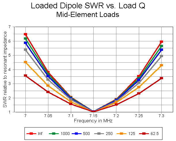
Now suppose that you are designing a 36' 40-meter dipole for hams to use. You have some design decisions to make. You can provide more gain with less operating bandwidth or more operating band width with less gain. Part of your decision will be based on expert judgment of at what point the gain decrease becomes operationally significant. The other part of your decision may be based on what you perceive to be demands of potential buyers in terms of operating bandwidth.
Remember that you may combine this exercise with the earlier one concerning antenna diameter and operating bandwidth. By using fatter elements, you may increase operating bandwidth for any given Q in the graphs, getting a modicum more gain in the process. However, both the weight and the cost of the resulting antenna will increase.
We can note in passing that fatter elements combined with inductors with naturally lower Qs will have a wider operating bandwidth than higher Q linear transmission line stub loads and smaller diameter elements. However, it is unlikely (from our full-size dipole graphs) that the increased gain of the fatter elements will completely offset the losses of lower Q loads. It is more likely that for equally carefully designed loads, one linear and the other an inductor, the narrow-banded linear- loaded dipole will have about a half dB advantage in gain on average, assuming the same antenna element length.
Which is the more important--operating bandwidth or gain--is a judgment call by the user based upon operating needs.
The half size-dipoles show a range of feedpoint impedances from about 26 ohms for a lossless load set to over 40 ohms for the lossiest set. If we assume the use of a matching network for the transition to 50-ohm coaxial cable, we have both network and other small losses that will slightly increase the operating bandwidth as measured at the network input terminals. If we measure the operating bandwidth at some distance down the coaxial line, we shall see a further increase in operating bandwidth based upon line losses. Hence, the contrast between 100 and 150 kHz in our example may in practice turn out to be a difference between 150 and 200+ kHz at the operating position. The exact amount of bandwidth increase depends on variables beyond the scope of this exercise to calculate. However, N6BV's transmission line and tuner loss program may be of use in analyzing each operator's situation.

We shall leave the loads in the elements just where we placed them in the dipole. In modeling terms, this appears as a percentage of distance from each end. As we adjust element lengths a bit for various reasons, the loads will move about a small amount, but not enough to disturb the general trends we want to observe. (If we were designing a real antenna, we might want to freeze the positions of the loads.) We shall continue to use the 11.375 microH inductances (511-ohm reactances) and adjust the element ends as needed to obtain various characteristics.
One of the easiest ways to design a Yagi is to set the elements at the desired spacing and then adjust the length of the driven element for resonance at the target frequency, in this case 7.15 MHz. Then, we might increase the length of the reflector for either maximum gain or maximum front-to-back ratio. The result would be a 2-element Yagi of excellent performance at the design frequency: at 70' up, over 11 dBi gain and over 30 dB front-to-back ratio with lossless loads. The resulting dimensions for the antenna are a driven element 17.67' long and a reflector 18.05' long. As the Q of the loads is decreased, the driven element must become longer to reset resonance within the +/- j1 Ohm reactance limit for the definition of resonance in this exercise. At the lowest Q of 62.5, the driven element is 17.80' long.
The antenna has some interesting properties, some of which may be graphed. However, let me present the frequency scan for the antenna using lossless loads to note one or two peculiar properties that are not evident in the graphs.
Frequency      Gain      Front-to-Back  SWR relative to
in MHz         in dBi    in dB          resonant impedance
7.00            9.75*     4.13*         23.904
7.05           10.26*     3.31*         17.229
7.10           10.95      3.55           6.242
7.15           11.20     30.43           1.001
7.20           10.14      9.95           1.704
7.25            9.47      6.17           2.227
7.30            9.08      4.50           3.309
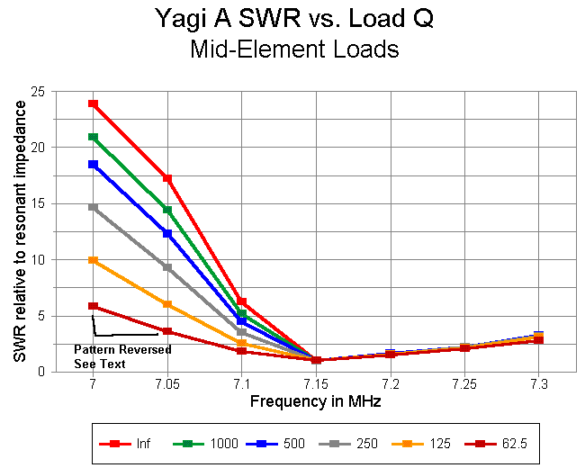
Most notable are the starred entries: at 7 to above 7.05 MHz, the antenna shows a reversed pattern, with gain to the rear. Hence, even apart from operating bandwidth SWR considerations, the antenna is useful only from about 7.1 MHz on upward. Only at the lowest Q in the following graphs does the region of reversed pattern drop below 7.05 MHz.
The remaining characteristics are reasonably well represented by the graphing of antenna performance with the same Q levels as we imposed upon the shortened dipoles. Antenna gain, as shown below drops significantly, especially when the load Qs drop below 250. Peak gain and peak front-to- back ratio are quite close to each other in frequency.

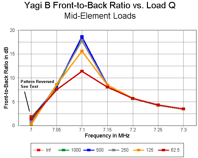
The front-to-back ratio shows a very sharp peak at the design frequency. Although gain drops steadily with decreasing load Qs, the front-to-back ratio actually increases for the first two steps of load Q decrease from the lossless load. This is natural. There appears to be for any 2-element design an optimum load Q for maximum front-to-back ratio at the design frequency. However, above the design frequency, front-to-back ratios closely coincide, with lowest Q front-to-back values actually exceeding those of higher Qs by an insignificant amount.
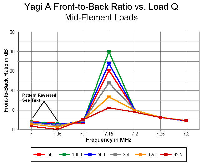
As a single-frequency 2-element beam design, this antenna is excellent. However, in operating bandwidth, the antenna is seriously deficient. It achieves a 150 kHz operating bandwidth only with the lowest Q loads, where the gain and the front-to-back ratio are mediocre at their peak. with a load Q of 250 or more, the operating bandwidth is barely 100 kHz. (As with the shortened dipole, these values are subject to increase depending where along the antenna-matching network-transmission line system that the measurements are made. The antenna shows a feedpoint impedance ranging from about 23 ohms for a lossless load set to nearly 39 ohms for loads with the lowest Q. Hence, a matching network may be presumed as part of the design.)
Although intriguing, the simple Yagi design is not satisfactory for most amateur 40-meter applications. How can we achieve greater operating bandwidth and preserve for each level of load Q all or most of the operating performance figures?
The answer lies largely in moving the performance peaks away from the resonant frequency of the antenna. Moving the performance peaks downward in frequency while holding the antenna resonance at the target design frequency of 7.15 MHz has the effect of changing the length ratio between the driven element and the reflector. From a design evolution standpoint, this means lengthening the reflector and then re-resonating the driven element. The reflector length will change more than the driven element length, thus altering the ratio of the two.
The process can go on until the designer is satisfied with the results. For this exercise, I chose to stop at a point perhaps short of where a practical designer might have gone. However, the resulting antenna is instructive with respect to several antenna properties. The basic properties of the antenna are illustrated in the following table of values corresponding to those of the earlier design, both list with lossless loads.
Frequency      Gain      Front-to-Back  SWR relative to
in MHz         in dBi    in dB          resonant impedance
7.00           10.09*     1.94*         16.424
7.05           11.50      7.84           5.283
7.10           10.80     18.27           1.411
7.15            9.86      8.39           1.006
7.20            9.30      5.58           1.384
7.25            8.96      4.20           2.086
7.30            8.74      3.38           3.214
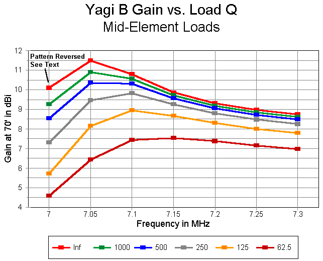
For this design, peak gain is very close to 7.05 MHz, where the pattern is now in the correct direction. Only at 7.00 MHz is the pattern reversed, and this would easily be resolved by scaling the antenna elements equally longer. The seemingly lower peak front-to-back ratio is actually well above 20 dB, but at a frequency between 7.07 and 7.08 MHz. Although the front-to-back ratio tapers rapidly. the gain holds up well across the band. Even at this very high load Q, operating bandwidth exceeds 170 kHz, a 70% increase from the previous model.
Incidentally, the driven element was 17.81' long, while the reflector was 18.35' long. This ratio of 1.03 R/DE is larger than that of the original model (1.02), and may be made larger still. As the operating bandwidth increases, however, performance begins to fall off for any given load Q level.
The following graph shows the gain of the antenna across 40 meters for each load Q level. Values are not significantly different from those of the preceding model, although the peak occurs at a lower frequency.
The graph of front-to-back ratios shows an increasing value down to about a load Q of 500. This is partly real and partly a function of the peak value gradually moving upward toward the 7.10 MHz frequency mark. As with the previous model, the front-to-back ratios for frequencies above the peak value are actually higher with lower load Q values.
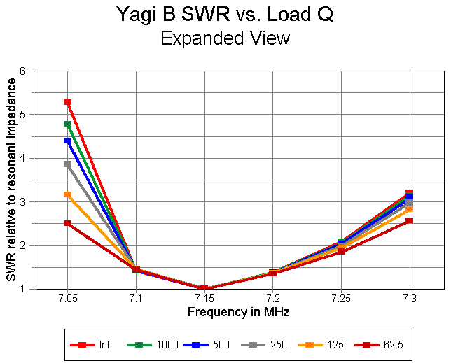
With respect to operating bandwidth, the general graph below, when compared to that for the earlier model, shows a distinct widening of operating bandwidth for all load Q levels.

Let's remove the high value for 7.00 MHz and redraw the graph. Now the difference among the Q levels are more apparent. At the lowest Q level, an operating bandwidth of 200 kHz is quite possible. Indeed, when measured at the operating position, the antenna might appear to cover almost the entire band. Alternatively viewed, the 200 kHz operating bandwidth, when measured at the operating position, might be obtainable with higher-Q loads.
Note that one may use all of the operating bandwidth widening techniques, even with this second design. Larger elements, measurements farther down the line, a line-to-antenna matching network, lower load Qs, and further separation of the resonant frequency from the peak performance frequency would all contribute to a wider operating bandwidth. The antenna showed a range of feedpoint impedances at resonance of about 36 for lossless loads to about 46 for a Q of 62.5. Further separation of the resonant frequency from the peak performance frequencies would likely result in an antenna that provided a direct match to 50-ohm coaxial cable.
There is a second way to increase the feedpoint impedance of the mid-loaded antenna: to move the loads outward. so far, we have used a stand mid- element spacing about 25% inward from the element ends. Let's change that spacing to about 20% inward from the element ends.
This takes us briefly back to the dipole. The first thing we discover with our 36' dipole is that the new loads must be larger to achieve resonance: 625 ohms each or 13.9 microH. The second discovery is that the feedpoint impedance (a value for resistance at resonance) climbs by about 10%. The following table compares the "25%" and the "20%" dipoles at 7.15 MHz with respect to gain and feedpoint impedance for values of Q from infinity down to 62.5:
Antenna:            "25%"                    "20%"
Q         Gain in dBi    Feed Z (R)     Gain in dBi    Feed Z (R)
lossless  7.40           26.32          7.41           28.87
1000      7.24           27.26          7.24           29.96
 500      7.10           28.20          7.09           31.06
 250      6.82           30.08          6.79           33.25
 125      6.30           22.90          6.25           37.63
  62.5    5.43           41.43          5.34           46.38
As Q decreases, the very slightly greater resistive losses result in a noticeable but operationally insignificant decrease in gain for the "20%" antenna relative to the "25%" model. The increase in feedpoint impedance, however, is high enough at reasonably achievable Qs (125-250) to permit the use of 50-ohm at the feedpoint. However, the SWR curves for each level of load Q are virtually indistinguishable from those for the "25%" model when SWR is related to resonant feedpoint impedance at the target design frequency (7.15 MHz).
The prospect of direct 50-ohm feeding of the "20%" antenna model improves as we translate the dipole design directly into a version of the wider-band Yagi shown above. The following table shows the gain, front-to-back ratio and SWR across 40 meters for the new model at a Q of 250. However, in this table, the SWR relative to a 50-ohm standard is shown.
Frequency      Gain      Front-to-Back  SWR relative
in MHz         in dBi    in dB          to 50 ohms
7.00            7.48*     1.31*         >10
7.05            9.27      7.71          >4
7.10            9.78     17.54           1.697
7.15            9.22      8.32           1.213
7.20            8.74      5.50           1.402
7.25            8.42      4.12           1.997
7.30            8.20      3.30           2.905
The 7.15 MHz resonance of the antenna is about 41 ohms, about 7% higher than that of the earlier "25%" model. Further juggling of the reflector- to-driver ratio and load placement might easily result in a direct 50-ohm feed antenna with a slightly wider operating bandwidth. Add to this a bit of reasonable element fattening, possibly a slightly lower Q, and measurement at the end of a prescribed feedline, and well over 2/3 of 40 meters can be within the perceived operating bandwidth of the antenna system.
Hopefully, understanding some of these (incompletely listed) aspects of
shortened antenna design will help you understand also some of the design
differences among shortened antennas on the market both today and in days
to come. Plug your own operating needs and desires into the equation, and
the result will likely be the most optimal antenna selection possible.
Updated 10-5-97. © L. B. Cebik, W4RNL. Data may be used for personal purposes, but may not be reproduced for publication in print or any other medium without permission of the author.