

Actually, the antenna itself is simplicity personified. Let's design it from two different angles.
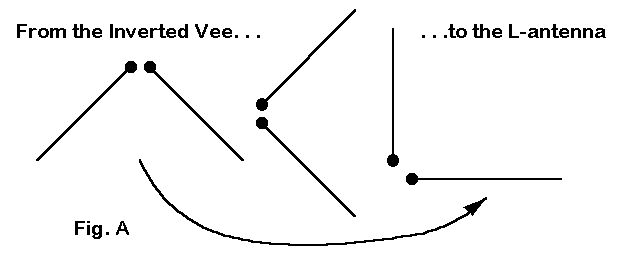
First, consider the common inverted Vee, shown in Figure A. When the legs make a 45-degree angle with the landscape or with a vertical line drawn between them, the impedance drops from the usual dipole value of 70 Ohms to about 50 Ohms. Let's imagine such a Vee with the apex about 30' in the air. Place a pin in the center feedpoint and start rotating the antenna until one leg is horizontal and the other points straight up. What happens to the convenient feedpoint impedance? Nothing. It remains in the 50-Ohm ball park.
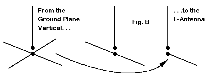
Let's try that again, but this time, begin with a 1/4 wavelength ground plane vertical with the base at the 30' mark, as shown in Figure B. This vertical antenna is actually a special type of dipole, one where one of the legs consists of 4 wires arranged symmetrically and at right angles to the vertical part. The radiation from the four horizontal legs cancels out, so the antenna has a vertically polarized pattern. We could have used any number of ground plane legs greater than 1, so long as they form a symmetrical arrangement to insure cancellation of horizontally polarized radiation.
But what happens if we have only one ground plane leg. There is no opposite member to cancel out the radiation. So, we have not only the vertically polarized radiation from the vertical leg, but also the horizontally polarized radiation from the horizontal leg.

What has happened is that the rotated Vee and the 1-legged vertical have turned into the same antenna, which is simply the L-Antenna. Figure 1 shows a sketch of how to build one from 3/8" diameter aluminum tubing. I claim no originality for the antenna, since a version of it has appeared in Moxon's Antennas for All Locations. Apparently, the first commercial version appreared in the 1950s.
Actually, you can build such an antenna out of any good antenna materials you have handy. Tubing from 3/8" to 1" diameter will work for the vertical element. Tubing or wire will do fine for the horizontal element. Spar- varnished wood, PVC, or other materials will make a good center mount.
With the version of the antenna shown, the design center or resonant frequency was set at 28.85 MHz. The feedpoint impedance is about 45.5 Ohms at that frequency. If you use larger diameter tubing, expect to shorten the elements a bit and find a slightly lower feedpoint impedance. If you use wire for some or all of the antenna, then expect to use longer dimensions and have a slightly higher feedpoint impedance.
Notice in the sketch that the vertical portion happens to be a little shorter than the horizontal portion. All that this means is that the antenna is fed very slightly off center and has a very slightly higher feedpoint impedance than if fed at the exact center.
Now consider that the usual hardware store tubing comes in 8' lengths. If you use a larger diameter vertical tube that is 8' long, then the horizontal section will have to be increased in length to resonate the antenna. The further distance off-center for the feedpoint will slightly raise the feedpoint impedance to offset the use of fatter tubing, at least in the vertical portion of the antenna.
The horizontal section can be tubing, especially if it runs off into thin air. If you mount this antenna on your roof, then you can run the horizontal wire or tubing along the ridge-top and support the opposite end.
Before deciding just how you want to run the antenna, consider the azimuth pattern for the antenna. The one shown in Figure 2 is modeled at a height of 30' above average ground where the elevation angle of maximum radiation is about 15 degrees.

Notice that the vertically polarized circle of radiation is slightly offset from being truly symmetrical around the antenna. That shift is due to the presence of the horizontal leg. The horizontally polarized radiation shows the typical dipole figure-8 pattern, but not as strong as it would be if both halves of the antenna were horizontal.
The total pattern is a mild kidney beam, with unequal side rejection amounts (-5 dB for the side with the leg and - 8 dB for the side without the leg). This total pattern is important only for skip communications. For local point-to-point communications, think about each of the sub- patterns. In planning an installation, try to orient the antenna so that the horizontal radiation covers the local areas of greatest communications interest. The vertical pattern will largely take care of itself.
The reason for taking such care in laying out the antenna is that cross- polarization of local radiation results in a large drop in signal strength. Skipping radiation through the ionosphere largely (but sometimes not completely) skews the polarization. So local coverage is the chief concern for laying out the L-antenna.

Figure 3 shows the elevation pattern of the antenna, again at 30 feet up. The pattern is taken through the axis of maximum gain, which is--for the total field--about 5 degrees off a true perpendicular line drawn to the horizontal element.
One of the advantages of the antenna for local work--or as a back-up for a more complex 10-meter antenna--is it broad operating bandwidth. By setting the resonant frequency up somewhat in the 10-meter band, the 2:1 SWR operating bandwidth of the antenna is the entire 10-meter band from 28.0 to 29.7 MHz. It may appear to be even wider, if readings are taken at the end of a length of coax.
For the record, here are the modeled impedance readings for the antenna across the band:
  Frequency           Feedpoint Impedance
  (MHz)               (R +/- jX Ohms)

 28.00                41.1 - j 31.0
 28.25                42.4 - j 21.7
 28.50                43.6 - j 12.5
 28.75                45.0 - j  3.2
 29.00                46.3 + j  6.1
 29.25                47.7 + j 15.4
 29.50                49.1 + j 24.7
 29.75                50.5 + j 34.1
Figure 4 shows the same information graphically. You should be able to obtain similar results across the band by judicious choice of materials and the feed point. Changing the lengths of the elements a little bit in either direction produces no significant change in performance.

Since materials and mounting positions will vary so much from one installation to another, I shall leave the construction details to you. I do recommend a height of over 25' for the base of the antenna, with a least a foot or two between the horizontal portion and any non-conductive rook top it might rest over. The greater the separation of the horizontal portion from other objects, the better the performance.
This antenna is not designed to compete in gain or directionality with any other type of antenna. Rather, it is designed to be simple, to provide both horizontal and vertically polarized radiation, and to have a feedpoint impedance that is compatible with common coaxial cable. As such, it can fill a useful niche in the array of ham antennas available for various purposes. The L-antenna is likely easy to scale to 12 meters as a utility antenna, but beyond that, may require some special effort to make it mechanically sound.
If you need a simple means to test the waters on 10 or to keep track of all the local operation, the L-antenna just might do the job for you--cheap and easy.
Updated 2-5-99. © L. B. Cebik, W4RNL. This item first appeared in AntenneX, Jul., 1998. Data may be used for personal purposes, but may not be reproduced for publication in print or any other medium without permission of the author.