

I have had occasion in the past to write on the W2EEY Expanded/Extended Lazy-H array that first appeared in the 1960s as a mono-band wire array. W6SAI later discovered that the antenna had available gain on frequencies in a range of at least 2:1. In other words, a 10-meter version of the antenna might be still useful on 20 meters.
My own looks into this antenna suggest an even wider range of utility, even though performance tapers off steadily as one lowers frequency. The chief drawback of the antenna has so far been the fixation on wire construction. I wondered what tubular elements might do, and the result is this preliminary note.
Large antenna farms for serious DX and contest use often have far more than one antenna per band. Hence, back-up on many bands is almost a matter of course. However, there is often only on antenna for each of the following bands: 40, 30, 17, and 12.
Now suppose there were a single rotatable antenna of relatively easy maintenance (compared to a 5-element Yagi or similar) that might provide emergency performance on 40 through 10 meters, performance that was not stellar, but usable in a crunch. Further suppose that the antenna had a top height of not more than say 70' (about 1/2 wl on 40 meters) and has elements no longer than some of the half-size 40-meter beams that are commercially available. Finally, suppose that the antenna required no boom, but looked more like one of those 40-meter beams flopped over to point straight up.
Such an antenna is not a mechanically simple installation, since 44' foot aluminum elements are not for the beginner. However, once installed, the antenna poses fewer stress problems than horizontally positioned arrays that require a boom. If it happened also be to bi-directional, then it might be laid close in to a pole or tower, since the total required rotation is 180 degrees.
There might be a niche for such an antenna, so the performance potentials and the installation challenges seem worth exploring, at least on a preliminary basis.
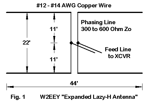
Fig. 1 shows the outlines of a typical extended Lazy-H in typical wire form. For many years, the Editors and Engineers Radio Handbook (edited by W6SAI) has carried that standard Lazy-H, fed at the bottom with a stub for coax matching for mono-band use. However, for multi-band use, a center junction of equal lengths of feedline is the simplest route to in-phase feeding on many bands.
The dimensions of the array for 10 meters are a modest 44' element length and 22' vertical separation. The EDZ element lengths represent the practical limit for use on HF bands, including 10 meters. Longer elements will yield a multi-lobe pattern on 10 meters.
The antenna height selected for study was a 66' top height. It can be mounted higher or lower with standard changes in the elevation angle of maximum radiation. However, a height of at least 66' seems advisable for reasonable 40-meter use.
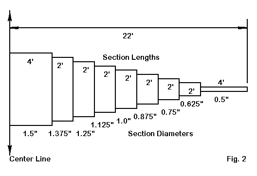
Fig. 2 shows the arrangement used to develop models. There is no assurance that this particular schedule meets appropriate standards. Any actual elements that one might contemplate constructing should be taken through an exercise or two on YagiStress to determine their mechanical feasibility. Although the schedule used here has proven very useful in comparing wire versions of the antenna to the most severe gradations I could think of, the element design is hypothetical only in mechanical terms.
The chief differences between the wire and tubing versions of the antenna were two. First, the models had many more wires. Second, the source impedances (as taken at the junction of the two feedlines from the elements to a center small segment) varied somewhat from those associated with the wire version.
For those unfamiliar with the extended Lazy-H, let's run a series of tabular entries and some patterns to check the potential performance. As with all models, these assume level, uncluttered terrain (average Sommerfeld-Norton ground) in NEC-4.1. Any serious antenna farmer has already run terrain analysis using N6BV or K6STI software and can therefore adjust the numbers for gain and elevation angles accordingly.
The figures in the first table focus on performance. The frequencies are band centers. Gain is maximum at the elevation angle of maximum radiation (TO angle). note that gain is bi-directional. The horizontal beamwidth is to the -3 dB points on the maximum gain curve.
Frequency      Gain      TO Angle       Horizontal          Notes
  MHz          dBi       degrees        Beamwidth (deg)
28.5           15.2       8             37             EDZ-type side lobes
24.94          14.7      10             41
21.225         12.6      11             52             Standard Lazy-H
18.118         11.0      13             61
14.175          9.1      17             73
10.125          8.2      24             85
 7.15           6.5      33             99
 7.15           7.2      29             89             Using top wire only
As the table shows, gain decreases steadily with frequency, since the elements grow shorter and the spacing narrower. The 10-meter gain is similar to a long-boom 5-element Yagi (without the front-to-back ratio). On 15, gain performance is similar to some 3-element Yagis, dropping to 2- element performance on 17. Below that frequency, the antenna becomes the equivalent of a rotatable dipole.
The patterns to follow, band by band, show the elevation patterns along the axis of maximum gain. Only spot azimuth patterns (for 10, 15 and 30 meters) are shown, since the evolution of the azimuth pattern with frequency changes is perfectly normal. One key advantage for the array is the relative absence of very strong high angle radiation, especially on the upper bands, thus reducing a potential noise source.
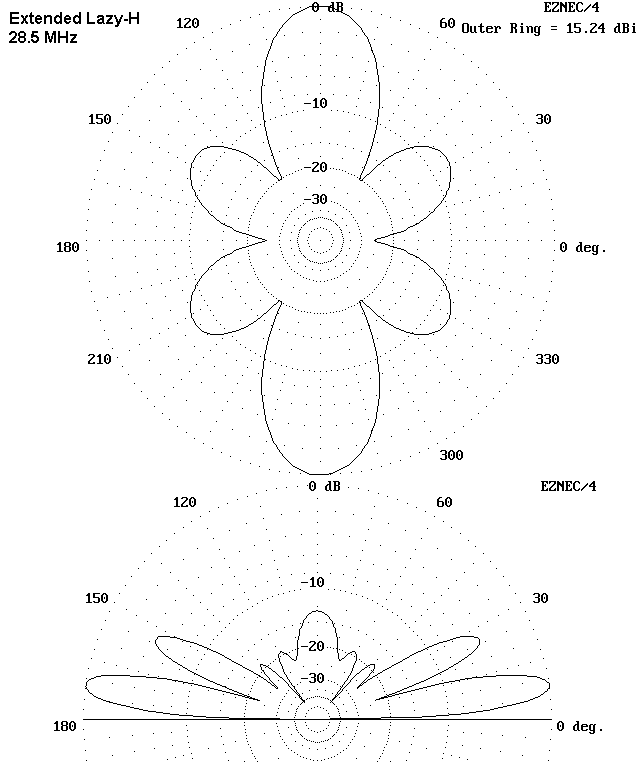
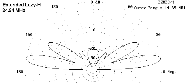
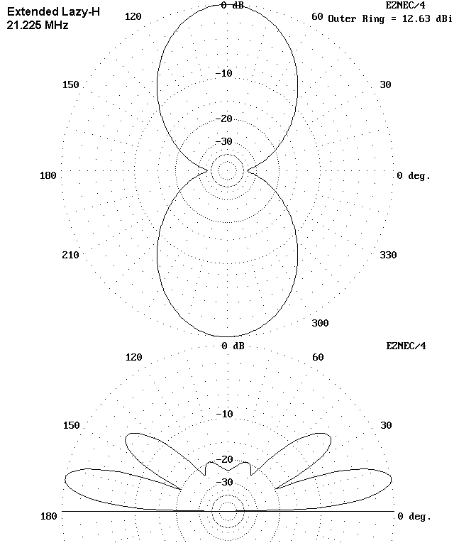
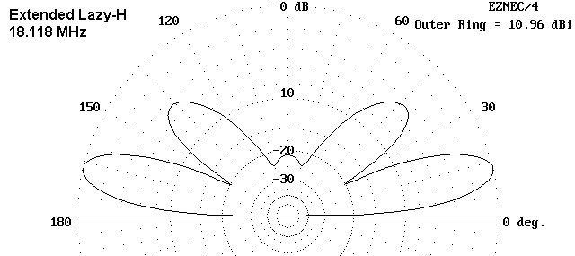
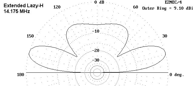
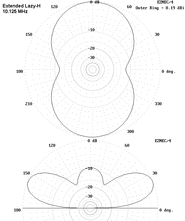
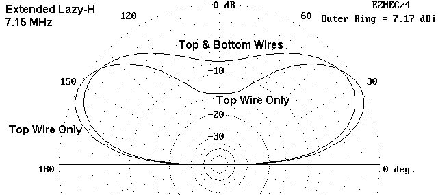
The 40 meter graphic shows two patterns, one for the use of both wires in phase, the other for the use of only the top wire. The latter is harder to implement in practice, but increases gain while lowering the take-off angle. On 30 meters, the use of only the top wire gives the appearance of lowering the take-off angle, but in fact, the bottom lines of the two patterns overlap, with the 2-wire system showing more gain. The seemingly unexpected result comes from a difference between vertical beamwidths for the two arrangements. Hence, on 30, the phased 2-wire system appears to offer superior overall performance.
The decrease in gain for each reduction in frequency is clearly apparent. given the array of antennas that inhabit some of the most extensive antenna farms, one might judge 20-meter performance to be the weakest in comparative terms. WARC band antennas tend to be simpler, and relative to them, the array is down by only a couple of dB at most. (If one has designed against these tendencies, then the differentials will also be different.) From 15 meters upward, the array gain is quite good--indeed, competitive might be a reasonable term. However, on 20, 5-element Yagis are fairly common (as are stacks of beams that give similar performance). The array on 20 yields performance similar to that of a 1 wl wire, perhaps 2 S-units weaker than the high-performance main antenna(s).
Nonetheless, the overall performance of the array relative to all of the antennas in use for every band must be accounted quite good in view of what the antenna is in this application: it is an emergency back-up capable of being switch in to replace any antenna system that goes dead when Murphy dictates. With a size similar to a half-size 40-meter 2-element Yagi pointing straight up, it is also much simpler than its most cogent competitor: a log-periodic for 40-10 meters.
With these constraints, the models yield the following source impedance calculations.
Frequency      Source Impedance         Notes
  MHz          R +/- jX Ohms
28.5           140 - j 655         Highly variable with change of Zo
24.94          335 + j 655         Somewhat variable with changes of Zo
21.225         110 + j  85         Decreases with Zo decreases
18.118         165 - j 135         Decreases with Zo decreases
14.175         880 - j 136         Highly variable with change of Zo
10.125          65 + j 250         Reasonably stable
 7.15           14 + j  10         Low and stable
 7.15           14 + j  30         Top-wire only in use, with line.
The number of cases in which the source impedance decreases with lower characteristic impedance phasing lines suggest that the highest feasible value of Zo be used for the antenna. Indeed, with lower values of Zo, the 40-meter source impedance can decrease below 10 Ohms, rapidly escalating the negative effects of loss sources in any installation.
High variability with changes in phasing line type tend to indicate that the builder of any antenna of this type may encounter quite different source impedances owing to minor local variations.
On the basis of these results (typical of several different models), there appear to be three initially plausible feed systems.
1. Parallel feedline and an ATU: The simplest feed system is to use parallel feedline from the juncture of the phasing lines to the operating position, with an ATU providing the requisite matching. for minimum loss in the matching system and for maximum isolation of equipment from common mode currents, a link-coupled tuner is recommended (with due construction precautions against unintended common mode paths). Without careful measurement of the actual source impedances encountered and equally careful measurement of the feedline length, there may be cases in which the impedance presented to the tuner terminals falls outside the range for which the tuner can effect a match while compensating for reactances at that point. Ordinarily, changing the line length in small increments will overcome this problem without incurring significant losses.
2. Remote switching of matching circuits--Version 1: A box of fair proportions installed at or very near the junction of the two phase lines might contain an array of circuits matching the source impedance on each band to standard 50-Ohm coaxial cable (or 75-Ohm hardline). The system would require a power source to control separate input and output sides of each network. The design of such a system would have to be a custom installation based on the actual source impedances of the system.
3. Remote switching of matching circuits--Version 2: A remotely switched matching network box mounted precisely at the junction of phase lines may present mechanical problems if the installation has a rotating mast joining the two elements. Moreover, the impedances to be matched may not be the most desirable. A length of open-wire parallel feeder from the phase line junction to some point further down the support structure may provide more desirable values and a more convenient mechanical installation. Since the variables of this modified system are so many, I have not explored any particular line lengths to check feasibility. Hence, electrically, this system can only be classed as equivalent to the first version.
Either remote matching system serves a certain preference among antenna farmers: the desire to present sensitive rigs and amplifiers with loads that require no in-shack tuning during intensive operations. All adjustments are made during installation and remade during routine maintenance. Those willing to make real-time adjustments and who can correctly install open-wire feeders may wish to use the simplest of the systems outlined here.
Of the three systems, only the remote box at the phase-line junction is amenable to easy switch-over to using only the top wire on 40 meters. Adapting the other systems to such use will be an exercise in ingenuity.
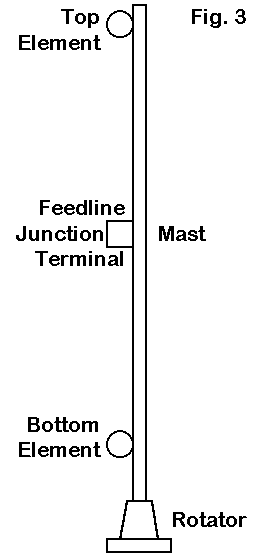
The basic elements of the antenna structure appear in Fig. 3.
No support structure is shown, since this aspect of the installation is subject to so many variations. The antenna itself consists of two 44' long elements of considerable weight. The top one will be 22' above the lower one, which might be considered a moderate stacking challenge to those with large antenna farms. Since the elements are mounted close to the line of the rotating support mast, the stresses they impose upon the assembly may be less than those of elements at the ends of a boom. A mast extension to handle a truss system to add support farther out along the elements is certainly feasible and may well be advisable.
If the lower element is (or both elements are) are side-mounted relative to a supporting pole or tower, then there will be a dead zone in the rotation. The size of this zone in degrees will vary inversely with the distance of the mast from the support structure. If we assume that there is a direction from the station that can be ignored, side-mounting may offer a means of installing the emergency antenna on an existing tower or pole. However, the elements may well interfere with existing guy wires.
These mechanical notes are offered on the premise that anyone thinking about this antenna has considerable experience with tall installations and can integrate the structure into a considerable backlog of diverse variables involved in high pole and high tower work. Those who may be reading these very preliminary notes without requisite experience should perhaps review some of the very considerable stack of reprints offer by Champion (K7LXC) before becoming too much attracted to the ideas noted here.
The aluminum extended Lazy-H is a bi-directional array with rotational capabilities that may make use of its reasonably narrow horizontal beamwidth on 40 through 10 meters. As such, it may fill a special niche, which I have termed the nearly-universal back-up for giant antenna farms. The feed system challenges are more electronic than they are mechanical--except for mounting and water-proofing a box for two of the suggested systems. Otherwise, the array presents fewer mechanical problems than most very large Yagis.
Still, the array not a cure-all for whatever ails. Nor is it a magic elixir for all antenna installations. The notes presented here simply suggest that for some installations, the antenna may provide that nearly universal back-up which is ever handy: ready to go on 40 to 10 meters when Murphy strikes down the primary antenna(s). Just do not tell Murphy you have installed one of these or he will take down your antennas two at a time.
Updated 2-12-99. © L. B. Cebik, W4RNL. Data may be used for personal purposes, but may not be reproduced for publication in print or any other medium without permission of the author.