 The Half-Square on 2 Meters
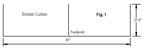
A bobtail curtain is two half squares with a common element. The common element is the center element of the array, and a convenient feedpoint is its junction with the long horizontal member. Essentially, the bobtail curtain is 3 phased vertical 1/2 wl apart, where the horizontal line forms the phasing line. As with the VHF half square, this is an antenna to consider if the need is for directional performance with vertically polarized signals.

Figure 1 shows a 2-meter bobtail curtain composed of 3/4" horizontal aluminum stick and 1/8" diameter vertical rods. I thread the rods and add nuts above and below the horizontal tube. I support the tube with a PVC assembly, but the only contact is with two Tee joints that pass over the horizontal tubing. This allows a center break, bridged by 1" L stock that holds the coax connector and supports the center rod.

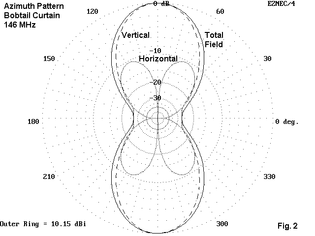
For a very narrow beamwidth (Figure 2) in a bi-directional vertically polarized array, the bobtail curtain is hard to beat. compare it pattern to that of the half square in the preceding section of these notes. The narrowing of the beamwidth yields added gain, about 0.75 dB more than the single half square. although the side insets are not quite so deep as those of the half square, the narrow beam width compensates. This antenna is quite good as a fixed vertical for repeater reception in areas that are troubled by interfering repeaters from the side. The gain is about 3 dB greater than a vertical dipole at the same height, and offending repeaters to the side can be as much as 25 dB below those toward which the antenna is aimed. The basic single bobtail has a feedpoint impedance of about 39 Ohms, and more exact matching to a 50-Ohm cable will be largely optional.
If one bobtail is good, will 2 be better?

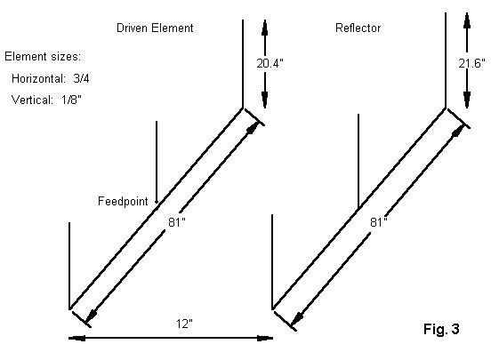
Figure 3 sketches the main elements of a 2 element bobtail curtain in a driver-reflector array. This parasitic extension of the half square beams requires only a foot of spacing, making the task of bracing the two horizontals fairly simple. The horizontals have the same length, while the verticals have different heights according to function. All 3 driver verticals are the same lengths as are all 3 reflector verticals. Feed arrangements for the driver are identical to those for the single bobtail.

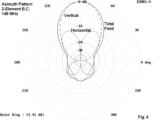
As shown in Figure 4, the bobtail beam provides a very interesting azimuth pattern (and all such patterns use the same 30 height, 3-degree elevation angle). The gain is about a half way between the gains of the 2- and 3- element half squares, and the front-to-back ratio exceeds 18 dB in a clean pattern. Feeding the center element gives the bobtail beam a symmetrical pattern. The feedpoint impedance is 51 Ohms according to both the model and prototype tests.
If one has a need for narrower beamwidth and the half square beams provide, then the bobtail beam may be a reasonable candidate among vertically polarized directional antennas. Like the 3-element half square, the antenna has 6 bristles to its hairdo, and this has led me to stop developments at this level. Actually, models of 3-element bobtails have not yielded good working feedpoint impedances to this date. However, some added gain and front-to-back ratio is feasible.
Whether the half square or bobtail beam are the right antennas to build depends on many variables of operating mode and conditions. They do present some overlooked possibilities--and even some further possibilities beyond these notes. In a year or two, it may be interesting to compare notes on the innovative methods of construction that might be used in building these parasitic vertical arrays.
Updated 4-12-99. © L. B. Cebik, W4RNL. Data may be used for personal purposes, but may not be reproduced for publication in print or any other medium without permission of the author. A more extended technical discussion of the antenna will appear next year in Communications Quarterly.