

These facts set up a small cluster of interesting questions. What is the HB9CV phased array, and how does it differ from the "ordinary" ZL-Special? The antenna has been so successfully built by so many European hams that it deserves more attention by US hams.
But before we look at the HB9CV, let's first look at what a claim for 3- element performance by a 2-element antenna might mean. Then we can make some intelligent evaluations of the performance claims.
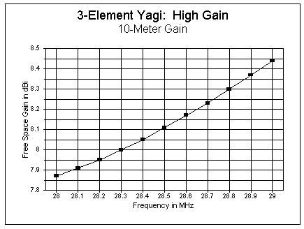
A high-performance, narrow band 3-element Yagi aims for the highest levels of gain and front-to-back ratio (in some form of a design balance) at the expense of a wide operating bandwidth--normally defined in terms of a 2:1 SWR ratio. The narrower bandwidth does not necessarily mean that the antenna will not operate with a 2:1 SWR ratio across any of the upper HF bands (or the first MHz of 10 meters). The following model antenna shows a gain of 8.1 dBi free space gain and a front-to-back ratio of over 27 dB at 28.5 MHz with better than 900 kHz of operating bandwidth. This performance is typical of what is possible with moderate boom-length 3-element Yagis.
                        3-Element Yagi:  High Gain
Element        Length in Feet      Spacing from Driven Element in Feet
Reflector           17.19                    5.2
Driven Element      16.41                    ---
Director            15.44                    6.0


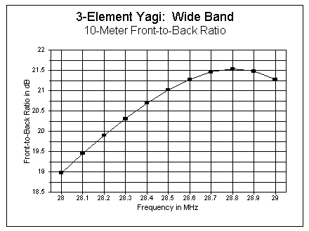
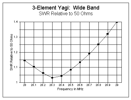
For wide bands, say from 10 meters on up, some 3-element monoband Yagi designers sacrifice some gain and front-to-back ratio for operating bandwidth. The following model shows an operating bandwidth that exceeds all of the 10-meter band (with a direct 50-ohm feed impedance). The design frequency of 28.5 MHz shows a gain of 7.0 dBi free space with a front-to- back ratio of about 21 dB. The gain is stable across the band, varying by about 0.25 dB, while the equally stable front-to-back ratio varies by only a little over 2 dB. A scaled version of the antenna covers all of 6 meters with ease.
                        3-Element Yagi:  Wide Band
Element        Length in Feet      Spacing from Driven Element in Feet
Reflector           17.83                    6.2
Driven Element      16.50                    ---
Director            14.67                    5.0

We can get more than 8.1 dBi free space gain from a narrow-band 3-element Yagi either by using a longer boom or by resizing and spacing elements--or both. In the process, we generally sacrifice front-to-back ratio. However, if we need a standard for 3-element monoband Yagis, the 8.1 dBi free space gain figure will do nicely, especially if we keep in mind the other properties of the antenna that make it desirable. The wide-band Yagi becomes, by comparison, somewhat of a special purpose antenna.
                      2-Element Yagi:  Typical Design
Element        Length in Feet      Spacing from Driven Element in Feet
Reflector           17.50                    4.3
Driven Element      16.00                    ---

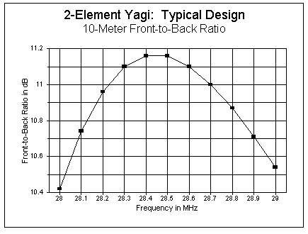

Unlike the stable 3-element Yagis, 2-element models show much greater variations of gain across the band. Gain varies by over 0.7 dB across the first MHz of 10-meters with this model, which is typical of the genre. The gain for this particular antenna peaks outside the 10-meter band at 27.3 MHz, with a figure of 7.04 dBi free space gain (with a front-to-back ratio of only 6.0 dB and a feedpoint impedance of about 16 ohms).
The 2-element Yagi is thus capable of better than 7 dBi free space gain--if we are willing to sacrifice other desirable antenna properties. More efficient at producing raw gain are 2-element Yagis using a director closely spaced to the driven element. With a spacing of 2.5', one such model shows (at 28.5 MHz) 6.73 dBi free space gain with a front-to-back ratio of over 22 dB and a feed point impedance of about 18 ohms. However, such beams have very narrow operating bandwidths. The subject model at 28 MHz shows only 5.9 dBi free space gain and a 2.7 SWR relative to the target frequency impedance. At 29 MHz, the gain reaches a peak of 7.38 dBi (free space), but the front-to-back ratio has dropped to 8 dB and the SWR is above 6:1 relative to the target frequency feedpoint impedance.
                2-Element Yagi:  Driven Element + Director
Element        Length in Feet      Spacing from Driven Element in Feet
Driven Element      17.10                    ---
Director            16.00                    2.5

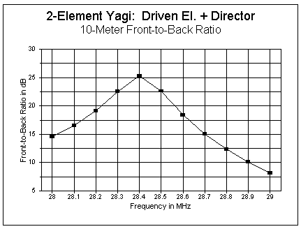

There are uses for such 2-element Yagis, if front-to-back ratio is of no concern and if feedpoint and matching losses can be accommodated or overcome. It is clear that, in terms of raw gain, it is possible to exceed the wide-band 3-element Yagi, although figures are still short of well- designed high performance 3-element Yagis.
The classic ZL and G manner of constructing such arrays is to use two dipoles--either equal in length or with the forward element shorter--spaced about 0.125 wavelengths apart with a length of standard parallel feedline between the two (with the half-twist, of course). For a phasing line, single-wire dipoles have usually used 70-ohm parallel line (almost impossible to come by today in power handling versions), while folded dipole models tend to use 300-ohm parallel line.
Phased arrays are usually designed to optimize front-to-back ratio as a mark of perfect phasing. The mathematics of the requisite current phasing were shown in "Modeling and Understanding Small Beams: Part 5: The ZL Special," Communications Quarterly, (Winter, 1997), pages 72-90. One interesting result was that standard Yagi dimensioning that shortens forward elements and lengthens rear elements must be set aside. At least one model required a rear element shorter than its forward partner to achieve so-called perfect phasing.
The number of design options using standard parallel transmission lines as the phasing element are not very many. Such designs tend to perform with respect to gain about on a par with well-designed 2-element Yagis with average forward gains of about 6.3 dBi free space. One would tend to prefer such an array only if the high front-to-back ratio (which can approach 50 dB at a target frequency) is needed. However, the rear null is quite frequency specific, and most such antennas will drop to a front-to- back ratio of under 20 dB within a half MHz of the target design frequency on 10 meters.
The following data is taken from 10th edition of Y21BK, Karl Rothammmel's Antennenbuch (Berlin: 1984) (graciously provided to me by Siegfried Rambaum, KB2YVC/DE8FGO). There are two versions of the antenna, one for balanced lines; the other for unbalanced lines. What the two antennas have in common is the basic dimensions of the elements. The forward element is 0.46 wavelengths long, while the rear element is 0.50 wavelengths long, with a spacing of 0.125 wavelengths. Y21BK reports that elements should be 0.47 and 0.51 wavelengths for antennas made from wire. For tubing (copper or aluminum), the recommended diameter is about 0.0025 wavelength.
Before examining the phasing and matching system, we can discover some interesting data about the potential of the antenna from the element recommendations. For 28.5 MHz, the dimensions call for 1" tubing spaced 51.77" (4.31') apart. The forward element is 190.5" (15.875') long, while the rear element is 210.31" (17.526') long.
Plugging these dimensions into a NEC or MININEC model and using separate sources for the front and rear elements, we can determine a number of things. First is the current magnitude and phase for the reversed rear element, relative to the forward element, to achieve maximum gain. A maximum free space gain of 7.32 dBi was achieved with a rear current magnitude of 0.90 of the forward element at a relative phase angle of -18 degrees (equivalent to 162 degrees standard rear element phasing). At this gain, the front-to-back ratio is 7.2 dB. These figures are quite similar to those of a similarly sized Yagi set for maximum gain.
Second, we can also determine the rear element relative current magnitude and phase to achieve maximum front-to-back ratio. With the model, a front- to-back figure of over 50 dB was achieved. However, as with all 2-element horizontal phased arrays, this figure represents the ratio in a direct line with the maximum forward gain lobe. It amounts to a deep dimple in the overall rearward lobe, which has a worst-case figure of about 20 dB down from the forward gain lobe. The requisite rear element relative current magnitude was 0.92 at a relative phase of -44 degrees (equivalent to 136 degrees standard rear element phasing). Antenna gain for this situation was about 6.37 dBi free space, or about 0.9 dB down from maximum gain.
Performance tapers gradually as the phase angle increases above -44 degrees and more rapidly as the current departs from the target magnitude. With lower relative current magnitudes and higher current phase numbers it is possible to achieve figures similar to those one might obtain with a constant 0.9 current magnitude and phase figures between -18 and -44 degrees.
The figure below outlines the complete HB9CV antenna, including the two versions of the matching network. The sketches are not to scale in order to permit the addition of the necessary dimensional annotations.
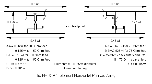
The dimensions in the sketches are for a feedpoint impedance for the balanced system of 150 ohms and for the unbalanced system of 75 ohms. Adjustment is essentially a matter of lengthening or shortening the length of the Tee or Gamma section (or the element length) until the proper feedpoint impedance is achieved.
Modeling a complete HB9CV system is not a simple task, because the antenna parts press the limits of both MININEC and NEC (2 or 4). The number of right angles in the system calls for complex wire length segment tapering or extremely small segment lengths, both of which exceed the maximum allowable number of segments within public domain MININEC. NEC produces inaccurate results with angular junctions of wires having dissimilar diameters or with closely spaced parallel wires of dissimilar diameters.
One potential solution is the use of a modeled transmission line between the forward and rear element matching "bars," a potential open only to NEC. The balanced system yielded quite plausible models when the Tee bars and connectors were increased to 1" diameter to match the main elements.
To reduce the effects of closely spaced element, which can introduce errors, the Tee bar was set at a 4" distance from the main element, both front and rear. Using check models with no feedline between the front and rear elements and with 2 sources (one on each of the Tee bars), NEC models showed a systemmatic variance of about 0.13 to 0.15 dB difference in gain and a difference of up to 1 dB in front-to-back ratio (between 20 and 30 dB ratios) from equivalent MININEC models, each fed with identical current magnitudes and phase angles. For the present exercises, these differences were considered not significant.
However, it is possible to construct models that give wholly unrealistic results. The HB9CV design is limited by the maximum gain and maximum front-to-back figures inherent in the element size and spacing relationships when dual sources are optimized for both magnitude and phase angle. Every matching system can only match: it cannot increase either maximum gain or maximum front-to-back ratio beyond the limits. Models that suggest higher gains are suspect, and turn out to commit one or more violations of NEC limitations. I have produced models showing up to 8.2 dBi free space gain with almost 28 dB front-to-back ratios: as appealing as these numbers are, they will not stand tests of convergence and independent source substitution.
Using most of common line impedances from 50 to 450 ohms along with sundry velocity factors, HB9CV models with Tee matching ranged in gain from 6.2 to 6.54 dBi free space. Front-to-back ratios ranged from 19.5 to 26.1 dB at the design center frequency, with lower values generally corresponding to higher gain figures.
The most stable nonsymmetrical model was a gamma-match system that used 1" elements throughout, even for the gamma bars and connectors, with a spacing of 4" between the element and gamma bars. The connecting transmission line was 75 ohm, 0.66 VF line. This model produced a very stable model between 28 and 29 MHz with a centerpoint source impedance of 53 ohms. However, the gain was only about 6.2 dBi, with a front-to-back ratio of 20 dB (+/-3 dB across the frequency span). The gain is only that of a normal 2-element Yagi, while the front-to-back ratio is about an S-unit better. This model falls well-within the range of models using a Tee-match system.
These models, of course, have limitations, since the Tee-bars and gamma-bars are not as specified within the HB9CV instruction set. However, nothing in a matching system, when physically modeled within the limits of any of the NEC programs, alters gain by more than 0.1 dB and front-to-back by more than about 0.5 dB. (See notes on the Tee match elsewhere in this collection.) The correspondence between the Tee-bar models with and without a connecting phasing line (using dual sources in the latter case) suggests that within broad limits, the models correctly report performances that one may obtain from the HB9CV.
A gain in the range of 6.4 to 6.5 dBi free space is an improvement over the standard 2-element Yagi. Front-to-back ratios between 20 and 26 dB represent improvements factors of 1.5 to 2.0 over the standard 2-element Yagi. Indeed, the QRM-killing ability of the HB9CV over the 2-element Yagi will likely be interpreted by operators as additional gain, given improvements in signal-to-noise ratio.
An additional advantage of the HB9CV is the flexibility of its matching design. Using almost any phasing line design, the Tee or gamma can be adjusted with respect to length and spacing from the main element to achieve a desired match, either with or without a transformer or balun. The antenna models showed good stability over a minimum of 750 kHz on 10 meters, and most covered more than the first MHz with under 2:1 SWR and very reasonable gain and front-to-back ratios at the operating band ends.
The following graphs show the free space gain, front-to-back ratio, and Matched SWR curves for two models: one a relatively high-gain model with a 300-ohm phase line, the other a relatively high SWR model with a 150-ohm phase line. The rates of change for both gain and front-to-back are less steep than those of standard 2-element Yagis. The feedpoint impedances are not 50-ohms, so matching was employed. The medium-gain, high-F-B model used a 1/4 wl 75-ohm match section, while the high-gain, medium F-B model used 3.3' of 75-ohm (VF=0.66) line to achieve a 50-ohm match. (The use of other than 1/4 wl sections of 75-ohm lines as matching sections to 50-ohm lines for reactive impedances in the 70-90 ohm range is a subject needing more widespread understanding, since it is a cheap and effective matching technique.)


The graphs show that it is relatively easy to develop a fine-performing HB9CV without too much concern for the exact phasing line impedance--and to match it to a 50-ohm feedline.
Despite these laudable properties, extensive modeling and model testing shows that the claims of gains above 7 dBi free space are supported only by faulty models to this point in the testing process. With a front-to-back (or front-to-rear) ratio of about 20 dB as a cut-off point for minimal rearward performance, gains have only approached 6.6 dBi maximum in all models tested. However, within the "normal" range of HB9CV figures, characteristics are stable across a wide operating bandwidth.
In the end, the HB9CV uses element phasing to excellent effect in yielding the most productive combinations of gain and front-to-back ratio achieveable from the basic geometry, combinations that cannot be achieved from parasitical operation alone. Moreover, it does so within a basic boom length of 1/8th wavelength. When well designed, it offers stable operating characteristics over a considerable bandwidth. Nonetheless, it remains an antenna subject to the physical limitations of its basic geometry.
One overlooked factor that the ZL-Special and the HB9CV have in common is the use of elements approximately 0.5 wl long. When the elements are fed by any phasing method that achieves high gain or maximum front-to-back ratio, the rear element shows an impedance of R - jX, while the forward element shows an impedance of R + jX. This condition sets limitations on direct phase-line interconnection of the two elements or--as with the HB9CV--requires special matching circuitry.
If both elements could be made to show inductive reactance at system resonance, then the element impedances could be tailored to simpler phase- line interconnection. The resistive component can be altered by varying the element length, while the reactance can be set by placing series capacitance at the element feedpoint.
In order to achieve this goal, both elements must be lengthened. Elements in the 0.7 region suffice to provide a direct 50-ohm feed using a phasing line between 75 and 150 ohms (with a velocity factor of 1.0). For the test model using 1" diameter elements, the forward element was 23.4' long (0.678 wl), while the rear element was 24.2' long (0.701 wl) with a spacing of 4.31' (0.125 wl). A 150-ohm open wire transmission line connects the two elements. The figure shows the antenna schematically.
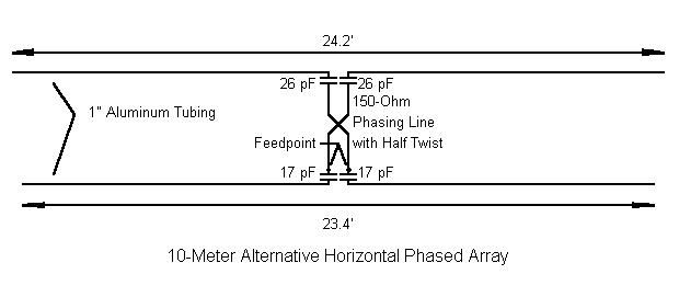
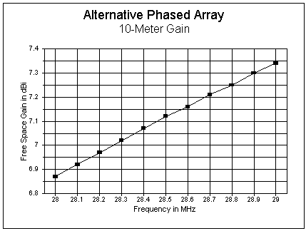
Because the elements are longer than 0.5 wl, they exhibit inherently more gain, which also translates into greater gain of the phased system. When the elements are separately fed, the array shows a maximum free space gain of 7.7 dBi when the rear element shows a current magnitude of 1.07 of the forward element at a relative phase angle of -18 degrees. (This figure is under 0.5 dB down from the narrow-band 3-element Yagi gain figure used as our standard.) The front-to-back ratio in this condition is only about 7.6 dB. Maximum front-to-back is better than 50 dB (with a free space forward gain of 6.8 dBi) when the rear element current is 1.27 of the forward element current with a phase angle of -44 degrees.
The actual array is designed for reasonable wide-band 50-ohm operation with a compromise between gain and front-to-back ratio. The following graphs display the anticipated performance across the first MHz of 10 meters.


A 150-ohm phasing line can be constructed from almost any wire from #14 to #10. #12 AWG copper wire requires 0.14" center-to-center spacing or 0.06" edge-to-edge spacing. Placing a piece of #14 AWG wire between 2 lengths of #12 wire achieves the correct spacing. Tape the wires and withdraw the center wire, replacing the center wire with a small insulated spacer at each tape point. The result is a 150-ohm parallel line. Keep the line taut to prevent shorts. Using #12 AWG enamel wire will not likely adversely affect the velocity factor by much.
The series capacitors can be standard value lumped components. However, one can also use lengths of smaller tubing, insulated by a tube (or rolled sheet) of teflon or other material for a tight but movable fit. Because of the number of variables involved in the tubing and insulating materials available, you will have to experiment to check the capacitance per inch of overlapping tubing to determine the correct amount for each elements.
One advantage of lumped components is that they can be brought out at right angles to the element. In this manner, if you are concerned that your phasing line has a velocity factor less than 1.0, you can use a slightly shorter length. However, slight changes in element spacing are less problematical than most experimenters are usually led to believe. Hence, you can adjust spacing and phase line length in small amounts for the best compromise.
The following figure shows the free space azimuth pattern of the suggested alternative phased array at 28, 28.5, and 29 MHz.
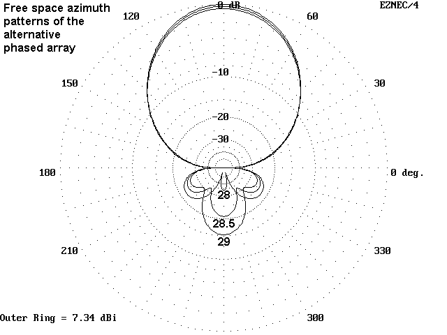
Hence, the alternative is largely a design exercise. The exercise demonstrates that understanding all aspects of each element, plus what occurs along a transmission line current transformer, provides a wealth of design opportunity for improving antenna performance. It is not enough to rely on a few broad antenna ideas. The goal should be to grow familiar with every possible aspect of both element and array condition and performance.
Has the limit been reached for maximizing gain while retaining a good front-to-back ratio and a workable feedpoint impedance in a 2-element array? I doubt it. The alternative design is simply a step in a certain direction. It exists because I asked why I should restrict myself to half- wavelength elements when longer elements offered some interesting advantages. The next design will come when I discover the right question to ask about another antenna.
Updated 2-10-98, 09-18-99. © L. B. Cebik, W4RNL. Data may be used for personal purposes, but may not be reproduced for publication in print or any other medium without permission of the author.