
 Part 4:
For example: many hams are familiar with the elevation patterns of horizontal antenna and can speak with assurance of take-off angles, secondary lobes, etc. But few are familiar with the patterns created by elevated vertical antennas. Therefore, as a small compendium, here are a few patterns taken with a model of an 8-radial 1/4 wl vertical. All patterns are over medium earth. Exact gain numbers are omitted (they will appear in tables later) because it is pattern shape that is our focal interest.
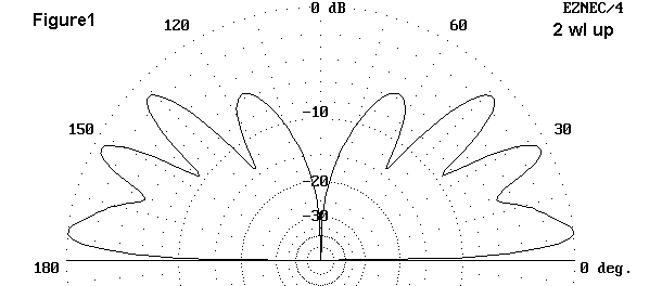
Figure 1 gives a representative high-altitude elevation pattern--280' on 40 meters. Patterns for antennas above and somewhat below this height are similar.
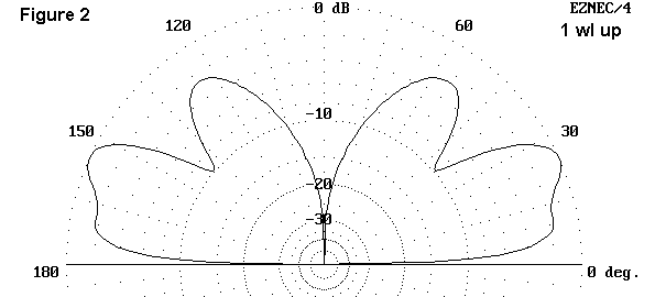
At 1 wavelength up, in Figure 2, the vertical begins to show the domination of a higher angle lobe. This pattern appears from grounds as good as salt water to poor earth.
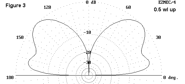
In Figure 3, at a half wavelength up, high angle radiation dominates, although over salt water, there is a strong lower lobe.
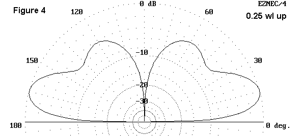
As is evident if Figure 4, when the base of the plane reaches about 0.25 wl, the lower lobe again dominates, although high angle radiation is readily apparent. A similar pattern appears as self-contained vertical 1 wl wire antennas are raised "too high."
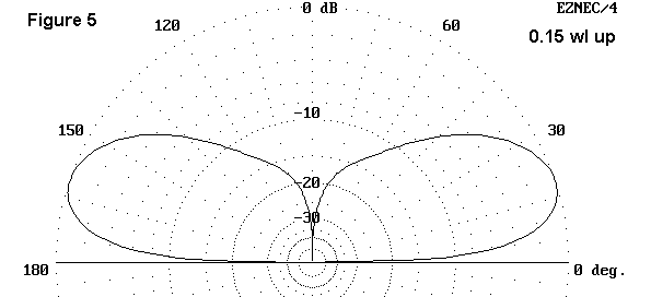
At about 0.15 wl between the ground and the base of the plane, as shown if figure 5, secondary lobes are virtually absent, with radiation concentrated in a single main lobe whose angle increases as soil conditions worsen.
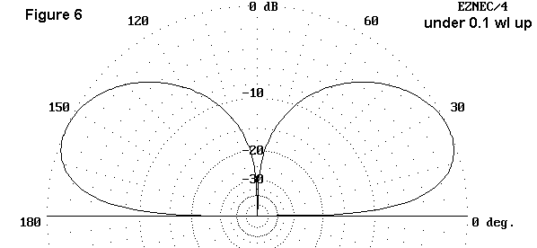
Below 0.1 wl, the pattern simply grows more bulbous, with lower gain and a higher elevation angle of maximum radiation. This pattern holds good as the plane is brought to ground and even below ground.
The patterns are typical of any ground plane antenna. A vertical dipole, however, presents some interesting variations--or perhaps compressions may be a better description. The vertical dipole has a widely separate feedpoint and element end. For feedpoint heights down to about 0.5 wl, the corresponding figures apply. Pattern changes compress below about 3.8 wl feedpoint height. At this height, the element end is about 20' off the ground at 40 meters, and the pattern resembles that if Figure 4 (ground plane at 0.25 wl). With the antenna end only 5' off the ground and the feed point nearly 40' up, the pattern is like Figure 4-5. Lowering the antenna just another 3' yields a pattern similar to Figure 4-6. Without bends or end hats, the true vertical dipole is just about at its lower limit.
We have already seen that the natural free space feedpoint impedance in ohms) of a quarter wavelength vertical with a plane is in the lower 20s, a value that also holds good at a 2-wl height. This feedpoint impedance value is at odds with experience when verticals are placed on or just above the ground. Additionally, ground and near-ground verticals do not exhibit the gain shown by the models at 2 wl up.
How do we account for the discrepancy? To see the answer to this, we need to look at models of ground plane verticals gradually lowered from their lofty heights to the earth. Fortunately, NEC-4 makes it possible not only to bring the plane close to earth, but--with the Sommerfeld-Norton ground system--to take the plane below ground.
It is important in looking at various planed-vertical models to seek out both differential and parallel alterations of fields and of feedpoint impedances as the models are lowered. Therefore, I have run several models through successive steps over four kinds of earth: perfect (which does not permit penetration), salt water with a conductivity of 5 S/m and a dielectric constant of 81 (for which height values within about 0.2' above the surface return faulty results, but for which sub-surface values of height are functional), very good earth with a conductivity of 0.0303 and a dielectric constant of 20, and medium/average earth with a conductivity of 0.005 and a dielectric constant of 13.
The tables list for each level both feedpoint impedance and elevation pattern values (maximum gain and take-off angle for that gain). It is important to remember that these are separate data. Feedpoint impedance is a function of the earth conditions just below the antenna and in its most immediate vicinity. Far field data are functions of earth conditions beginning at some distance (something at least over a wavelength, if not farther) from the antenna. If the conditions under the antenna have been improved, then the feedpoint impedance of "very good ground" might apply, but the far field might still be no better than that shown for "medium" earth. Conversely, island operations might show "medium" earth impedances while giving salt water far field results.
Table heights are listed in feet, and are given for the feedpoint. The tables must be read with two understandings. First, a wavelength at the target frequency of 7.05 MHz is about 140' long, so that the table begin at 2 wl, with check point at 1.5, 1.0, 0.5, 0.375, 0.25, 0.15 wl and lower. Second, in accord with the model construction technique described in the last episode, the plane will be 1' below the feedpoint. At upper heights, this difference makes no difference, but becomes increasingly important at the lowest heights, e.g., 20 10, 5, 1.5, 1.2, 1.1, and 0 feet up. There are two zero feet feedpoint values, one with a modified model for plane wires buried 0.5' down; the other unmodified with plane wires 1.0' below the surface. The modified model appears not to have introduced unreasonable numbers for the plane 0.5' below surface.
Commentary on the tables will appear afterwards.
Vertical Dipole (for reference):  2" dia.  al. element, 66.5' long
Free space:  Gain:  2.13 dBi; Feed Z:  71.98 - 0.85 ohms

          Perfect Earth                      Salt Water
Height    Feed Z         Gain/TO angle       Feed Z         Gain/TO angle
(feet)    (R +/- jX)     (dBi/degrees)       (R +/- jX)     (dBi/degrees)
280-2wl   71.75 - 0.82   8.16 / --           71.75 - 0.82   7.54 / 14
210-1.5   71.56 - 0.81   8.17 / --           71.57 - 0.81   7.31 / 19
140-1wl   71.02 - 0.81   8.21 / --           71.03 - 0.80   6.45 / 28
 70-0.5   67.82 - 1.10   8.40 / --           67.85 - 1.07   7.22 /  5
 52.5     73.02 - 8.99   8.05 / --           72.97 - 8.95   7.06 /  5
 43.25    83.92 - 8.03   7.46 / --           83.81 - 8.06   6.59 /  6
 38.25    93.00 - 1.17   7.07 / --           92.90 - 1.28   6.25 /  6
 35-.25   101.3 + 11.0   6.80 / --           101.8 + 10.7   6.02 /  7

          Very Good Earth                    Medium Earth
Height    Feed Z         Gain/TO angle       Feed Z         Gain/TO angle
(feet)    (R +/- jX)     (dBi/degrees)       (R +/- jX)     (dBi/degrees)
280-2wl   71.78 - 0.79   5.18 / 13           71.83 - 0.79   4.44 /  7
210-1.5   71.62 - 0.76   5.45 / 18           71.71 - 0.75   3.43 /  9
140-1wl   71.14 - 0.68   5.21 / 27           71.34 - 0.63   3.52 / 27
 70-0.5   66.21 - 0.48   1.25 / 14           68.99 - 0.15   0.20 / 13
 52.5     71.79 - 8.39   2.09 / 12           71.00 - 7.05   0.35 / 15
 43.25    82.01 - 9.07   2.15 / 13           79.21 - 8.90   0.23 / 16
 38.25    91.25 - 3.82   2.07 / 14           87.86 - 5.76   0.07 / 17
 35-.25   101.0 + 6.95   1.98 / 15           97.89 + 3.14   0.11 / 18
Notes: The pattern of feedpoint impedance does not change significantly as one changes the soil type beneath the antenna. The greatest change occurs close to the ground with the transition from very good to medium earth, and a similar change will likely be noted in the transition from medium to poor earth.
Variable in antenna gain and take-off angle are noticeable with changing far field earth conditions. However, most notable is the sudden decrease in gain over very good and medium earth between 1 wl and 0.5 wl heights. Low-mounted vertical dipoles with salt-water paths are capable of approximately 6 dB better performance than the same antenna with medium earth paths.
1/4 wl Vertical (2" dia.  al. element, 33.25' long), with 4 0.25" radials
each 35.6' long, set 1' below the feedpoint
Free space:  Gain:  1.38 dBi; Feed Z:  22.88 - 0.18 ohms

          Perfect Earth                      Salt Water
Height    Feed Z         Gain/TO angle       Feed Z         Gain/TO angle
(feet)    (R +/- jX)     (dBi/degrees)       (R +/- jX)     (dBi/degrees)
280-2wl   22.90 - 0.18   7.39 / --           22.90 - 0.18   6.94 / 13
210-1.5   22.92 - 0.94   7.39 / --           22.92 - 0.10   6.87 / 18
140-1wl   22.96 + 0.12   7.38 / --           22.97 + 0.11   6.53 / 26
 70-0.5   23.30 + 1.01   7.33 / --           23.30 + 0.99   5.98 /  4
 52.5     20.90 + 0.49   7.80 / --           20.93 + 0.50   6.63 /  5
 35-.25   21.14 - 3.55   7.71 / --           21.12 - 3.49   6.75 /  6
 20-.15   27.08 - 5.53   6.62 / --           26.95 - 5.51   5.86 /  7
 10       33.72 - 2.05   5.71 / --           33.53 - 2.19   5.08 /  8
  5       37.46 + 3.37   5.31 / --           37.30 + 3.09   4.73 /  9
  1.5     40.03 + 12.9   5.09 / --           41.21 + 14.2   4.40 /  9
  1.2     39.94 + 14.8   5.10 / --
  1.1     39.82 + 15.4   5.12 / --
  0-.5                                       37.23 + 1.09   4.45 /  9
  0-1.0                                      38.31 + 1.96   4.33 /  9

          Very Good Earth                    Medium Earth
Height    Feed Z         Gain/TO angle       Feed Z         Gain/TO angle
(feet)    (R +/- jX)     (dBi/degrees)       (R +/- jX)     (dBi/degrees)
280-2wl   22.91 - 0.20   5.07 / 27           22.91 - 0.22   3.88 /  6
210-1.5   22.94 - 0.13   4.85 / 17           22.94 - 0.17   3.21 / 36
140-1wl   23.01 + 0.05   5.09 / 25           23.01 - 0.04   3.24 / 24
 70-0.5   23.42 + 0.79   3.49 / 44           23.42 + 0.51   2.33 / 44
 52.5     21.26 + 0.68   1.71 / 52           21.68 + 0.66   0.73 / 52
 35-.25   20.84 - 2.90   1.86 / 12           20.91 - 2.16   0.14 / 15
 20-.15   25.73 - 5.69   2.02 / 15           24.49 - 5.13   0.19 / 18
 10       32.40 - 3.87   1.81 / 18           30.36 - 4.48   0.02 / 22
  5       37.14 + 1.01   1.64 / 19           34.82 - 0.44   -.13 / 24
  1.5     43.72 + 22.6   1.24 / 21           40.64 + 21.1   -.46 / 25
  1.2     45.84 + 37.3   1.04 / 20           42.94 + 35.5   -.65 / 25
  1.1     49.03 + 52.1   0.75 / 21           46.61 + 49.0   -.94 / 25
  0-.5    52.63 + 12.9   0.33 / 21           67.38 + 13.7   -2.6 / 26
  0-1.0   54.11 + 17.4   0.21 / 21           68.62 + 18.6   -2.6 / 26
Notes: There are numerous things to notice about this table set. With respect to feedpoint impedance, note the slight rise at 70' (1/2 wl), just where the vertical dipole impedance dipped. Although NEC-4 does not return sensible values for planes set at distances of 0.2' and 0.1' above the surface, the values for the plane set below ground provide an indication of the standard monopole feedpoint impedance values when the antenna is mounted without a plane but in contact with perfect earth. However, these values increase rapidly with a degradation in earth quality immediately under the antenna. Moreover, the resonance of the system is also disturbed--with a further shortening of the radials as the indicated need. Shortening the radials will also slightly lower the value of the resistive component of the feedpoint impedance. The progression of increase in feedpoint impedance begins as the antenna is lowered below the 0.25 wl point, whatever the ground type.
The far field pattern displays a variability in the angle of the lowest lobe, depending on the type of far field ground. In the region from 0.375 wl through 1 wl over very good and worse earth, high angle radiation dominates the pattern. Over these same earths, the gain takes a sudden nose-dive below the 0.5 wl antenna height, but progresses more smoothly down over slat water and better. At a certain height which varies with the level of earth quality, the take-off angle of low-mounted antennas reaches a minimum and then rises as the antenna is brought lower, including with the plane below the surface. The differential in gain between the value for a 2 wl height and for the lowest height modeled increases as the earth condition values decrease.
1/4 wl Vertical (2" dia.  al. element, 33.25' long), with 8 0.25" radials
each 34.5' long, set 1' below the feedpoint
Free space:  Gain:  1.34 dBi; Feed Z:  23.03 - 0.06 ohms

          Perfect Earth                      Salt Water
Height    Feed Z         Gain/TO angle       Feed Z         Gain/TO angle
(feet)    (R +/- jX)     (dBi/degrees)       (R +/- jX)     (dBi/degrees)
280-2wl   23.05 - 0.06   7.36 / --           23.05 + 0.06   6.91 / 13
210-1.5   23.06 - 0.14   7.36 / --           23.06 + 0.14   6.84 / 18
140-1wl   23.11 + 0.36   7.35 / --           23.11 + 0.35   6.49 / 26
 70-0.5   23.42 + 1.25   7.30 / --           23.43 + 1.23   5.95 /  4
 52.5     21.03 + 0.69   7.77 / --           21.06 + 0.70   6.60 /  5
 35-.25   21.34 - 3.35   7.66 / --           21.33 - 3.30   6.71 /  6
 20-.15   27.38 - 5.26   6.56 / --           27.26 - 5.24   5.80 /  7
 10       34.08 - 1.84   5.66 / --           33.89 - 1.99   5.02 /  8
  5       37.81 + 2.76   5.26 / --           37.59 + 2.40   4.69 /  9
  1.5     40.45 + 9.97   5.04 / --           40.38 + 9.71   4.48 /  9
  1.2     40.25 + 11.8   5.07 / --
  1.1     39.95 + 13.1   5.10 / --
  0-.5                                       37.23 + 1.09   4.45 /  9
  0-1.0                                      38.32 + 1.95   4.33 /  9

          Very Good Earth                    Medium Earth
Height    Feed Z         Gain/TO angle       Feed Z         Gain/TO angle
(feet)    (R +/- jX)     (dBi/degrees)       (R +/- jX)     (dBi/degrees)
280-2wl   23.06 + 0.04   5.04 / 27           23.06 + 0.02   3.85 /  6
210-1.5   23.08 + 0.11   4.82 / 17           23.08 + 0.07   3.17 / 36
140-1wl   23.15 + 0.29   5.06 / 25           23.15 + 0.21   3.21 / 24
 70-0.5   23.55 + 1.03   3.44 / 45           23.56 + 0.76   2.27 / 44
 52.5     21.39 + 0.89   1.63 / 52           21.81 + 0.88   0.65 / 52
 35-.25   21.02 - 2.71   1.82 / 12           21.08 - 1.96   0.11 / 15
 20-.15   26.03 - 5.47   1.96 / 15           24.76 - 4.93   0.15 / 19
 10       32.74 - 3.84   1.76 / 18           30.65 - 4.60   0.03 / 22
  5       37.17 - 0.44   1.64 / 20           34.80 - 2.36   -.14 / 24
  1.5     40.66 + 10.3   1.55 / 21           37.87 + 7.47   -.19 / 25
  1.2     40.93 + 19.5   1.53 / 20           38.54 + 16.0   -.23 / 26
  1.1     41.84 + 28.0   1.43 / 21           39.84 + 22.9   -.34 / 26
  0-.5    47.37 + 11.1   0.81 / 21           54.61 + 12.6   -1.5 / 26
  0-1.0   49.19 + 16.3   0.66 / 21           56.33 + 18.5   -1.6 / 26
Notes: For all values over perfect earth and salt water, and for all values down to a low antenna height, the differences in numerical values between the 4-radial and 8-radial models parallel those between the respective free space models.
At heights below 5' (plane at 4' or less), the 8-radial model shows significant improvements. with the plane above the earth, the impedance does not rise as fast as that of the 4-radial model. The seeming anomaly of a lesser increase at low heights for the model over medium earth relative to the model over very good earth is more apparent than real. With smaller increases in reactance at those levels, the overall nonresonant condition is less radical than that of the model over very good earth. Bringing the model over very good earth back to resonance will lower the resistive component and make the values more comparable.
With the plane below the surface, feedpoint reactances are similar to those for the 4-radial model, but the resistive component values are significantly less.
With the plane below 5' (0.035 wl), the 8-radial model begins to exhibit significant improvements in gain over the 4-radial model over very good or worse earth. With the planes below the surface, the improvement is greater than 1 dB. With the planes higher than 5' above ground, gain differences are insignificant.
1/4 wl Vertical (2" dia.  al. element, 33.25' long), with 16 0.25" radials
each 32.5' long, set 1' below the feedpoint
Free space:  Gain:  1.38 dBi; Feed Z:  22.80 + 0.06 ohms

          Perfect Earth                      Salt Water
Height    Feed Z         Gain/TO angle       Feed Z         Gain/TO angle
(feet)    (R +/- jX)     (dBi/degrees)       (R +/- jX)     (dBi/degrees)
280-2wl   22.81 + 0.17   7.40 / --           22.81 + 0.17   6.94 / 13
210-1.5   22.82 + 0.25   7.40 / --           22.82 + 0.25   6.87 / 18
140-1wl   22.86 + 0.47   7.40 / --           22.86 + 0.46   6.51 / 26
 70-0.5   23.12 + 1.35   7.36 / --           23.13 + 1.33   6.01 /  4
 52.5     20.82 + 0.69   7.81 / --           20.84 + 0.70   6.64 /  5
 35-.25   21.33 - 3.28   7.66 / --           21.31 - 3.22   6.71 /  6
 20-.15   27.48 - 4.82   6.54 / --           27.36 - 4.82   5.79 /  7
 10       34.15 - 0.92   5.64 / --           33.97 - 1.08   5.01 /  8
  5       37.84 + 3.92   5.25 / --           37.64 + 3.46   4.68 /  9
  1.5     40.59 + 9.50   5.02 / --           39.93 + 8.42   4.53 /  9
  1.2     40.60 + 10.0   5.03 / --
  1.1     40.23 + 11.1   5.07 / --
  0-.5                                       37.25 + 1.08   4.45 /  9
  0-1.0                                      38.34 + 2.49   4.33 /  9

          Very Good Earth                    Medium Earth
Height    Feed Z         Gain/TO angle       Feed Z         Gain/TO angle
(feet)    (R +/- jX)     (dBi/degrees)       (R +/- jX)     (dBi/degrees)
280-2wl   23.82 + 0.15   5.05 / 27           22.82 + 0.13   3.88 /  6
210-1.5   22.84 + 0.22   4.86 / 17           22.84 + 0.18   3.16 / 36
140-1wl   22.90 + 0.40   5.08 / 25           22.91 + 0.32   3.24 / 24
 70-0.5   23.25 + 1.14   3.40 / 45           23.27 + 0.88   2.24 / 44
 52.5     21.15 + 0.90   1.53 / 52           21.56 + 0.91   0.57 / 52
 35-.25   20.98 - 2.67   1.84 / 12           20.99 - 1.93   0.13 / 15
 20-.15   26.16 - 5.13   1.96 / 15           24.86 - 4.70   0.14 / 19
 10       32.99 - 3.04   1.75 / 18           30.96 - 4.01   -.06 / 22
  5       37.52 + 0.52   1.61 / 20           35.32 - 1.73   -.20 / 24
  1.5     40.61 + 5.86   1.57 / 21           38.15 + 2.87   -.24 / 25
  1.2     39.38 + 9.51   1.71 / 20           37.55 + 7.21   -.15 / 26
  1.1     39.17 + 15.0   1.73 / 21           38.21 + 11.3   -.21 / 26
  0-.5    43.41 + 9.01   1.20 / 21           44.90 + 10.3   -.63 / 26
  0-1.0   45.41 + 15.2   1.04 / 21           46.88 + 16.9   -.74 / 26
Notes: Once more, most differences in numerical values parallel the differences in free space models. The most notable differences occur over very good or worse earth at antenna height below 5' (plane below 4'). Doubling the number of radials to 16 drops the very good earth impedance by about 5 ohms and the medium earth impedance by 10 ohms, the same rate of change as between 4 and 8 radials. Reactance at low levels also decreases further, except as the plane goes below the surface.
Above ground gain, even at very low heights, increases only marginally. However, there is nearly a 0.9 dB increase in gain for the models with the plane below the surface--a 1.9 dB increase over the 4-radial models.
1/4 wl Vertical (2" dia.  al. element, 33.25' long), with 32 0.25" radials
each 30.0' long, set 1' below the feedpoint
Free space:  Gain:  1.45 dBi; Feed Z:  22.39 - 0.37 ohms

          Perfect Earth                      Salt Water
Height    Feed Z         Gain/TO angle       Feed Z         Gain/TO angle
(feet)    (R +/- jX)     (dBi/degrees)       (R +/- jX)     (dBi/degrees)
280-2wl   22.40 - 0.28   7.47 / --           22.40 - 0.28   6.99 / 13
210-1.5   22.41 - 0.21   7.47 / --           22.41 - 0.21   6.93 / 18
140-1wl   22.43 + 0.01   7.47 / --           22.43 + 0.01   6.55 / 26
 70-0.5   22.63 + 0.88   7.44 / --           22.64 + 0.87   6.10 /  4
 52.5     20.44 + 0.11   7.87 / --           20.47 + 0.12   6.72 /  5
 35-.25   21.19 - 3.73   7.68 / --           21.17 - 3.68   6.73 /  6
 20-.15   27.41 - 4.86   6.54 / --           27.30 - 4.87   5.79 /  7
 10       34.00 - 0.42   5.66 / --           33.84 - 0.58   5.03 /  8
  5       37.63 + 4.99   5.27 / --           37.46 + 4.62   4.70 /  9
  1.5     40.39 + 11.0   5.04 / --           39.63 + 9.68   4.56 /  9
  1.2     40.60 + 11.0   5.02 / --
  1.1     40.42 + 10.9   5.05 / --
  0-.5                                       37.25 + 1.07   4.45 /  9
  0-1.0                                      38.35 + 1.92   4.33 /  9

          Very Good Earth                    Medium Earth
Height    Feed Z         Gain/TO angle       Feed Z         Gain/TO angle
(feet)    (R +/- jX)     (dBi/degrees)       (R +/- jX)     (dBi/degrees)
280-2wl   22.41 - 0.29   5.09 / 27           22.42 - 0.31   3.94 /  6
210-1.5   22.43 - 0.23   4.92 / 17           22.44 - 0.27   3.18 / 37
140-1wl   22.48 - 0.04   5.12 / 25           22.49 - 0.12   3.29 / 24
 70-0.5   22.77 + 0.69   3.38 / 45           22.81 + 0.44   2.22 / 44
 52.5     20.74 + 0.33   1.44 / 53           21.15 + 0.38   0.48 / 51
 35-.25   20.81 - 3.17   1.90 / 12           20.76 - 2.45   0.17 / 15
 20-.15   26.15 - 5.28   1.98 / 15           24.83 - 4.96   0.15 / 19
 10       33.05 - 2.63   1.75 / 18           31.11 - 3.83   -.07 / 22
  5       37.70 + 1.53   1.60 / 20           35.70 - 1.07   -.24 / 24
  1.5     41.47 + 6.44   1.49 / 21           39.32 + 2.54   -.39 / 25
  1.2     40.09 + 7.45   1.65 / 21           38.59 + 4.60   -.30 / 26
  1.1     38.41 + 10.1   1.82 / 21           38.49 + 6.85   -.28 / 25
  0-.5    40.54 + 7.19   1.48 / 21           38.83 + 6.15   -.17 / 26
  0-1.0   42.51 + 14.1   1.33 / 21           40.34 + 13.4   -.24 / 26
Notes: Above ground mounting of the antenna and plane yields performance that improves slightly in only one area: the degree of reactance induced at the feedpoint by close mounting to the ground. Performance actually degrades in other categories, but by amounts that are either insignificant or not especially reliable. Indeed, the improvement in gain between the 4- radial model and the 32-radial model at plane heights of 4 to 9 feet is only about 0.1 dB
When the plane is below the surface, the feedpoint reactance continues to drop, but by lesser amounts than with other radial doublings. Gain improvements amount to less than 0.3 dB over very good ground and by less than 0.5 over medium earth. Doubling the number of radials once more may be dubious if the far field earth is very good, but may bring about further gain improvements (in the neighborhood of 0.25 dB) if the path ground is medium or worse. Because of time constraints, 64-radial plane modeling has not been more than sampled.
All of these antennas constitute tuned systems (in the sense noted in passing by Moxon): they are resonant (or at very low heights, near resonant) antennas. Planes have been modeled just as would any open-spoke hat system for shortening the length of an antenna elements.
Since hats can be modeled with spokes plus a perimeter wire, I decided to model a 1/4 wavelength vertical with a plane of this design. A 4-spoke + perimeter model was constructed and run through the same exercise as all of the open-spoke models.
1/4 wl Vertical (2" dia.  al. element, 33.25' long), with 4 0.25" radials
each 19.4' long, with a perimeter wire forming a square, all set 1' below
the feedpoint
Free space:  Gain:  1.70 dBi; Feed Z:  20.76 - 0.60 ohms

          Perfect Earth                      Salt Water
Height    Feed Z         Gain/TO angle       Feed Z         Gain/TO angle
(feet)    (R +/- jX)     (dBi/degrees)       (R +/- jX)     (dBi/degrees)
280-2wl   20.75 - 0.51   7.72 / --           20.75 - 0.51   7.20 / 14
210-1.5   20.74 - 0.45   7.72 / --           20.74 - 0.45   7.11 / 18
140-1wl   20.71 - 0.27   7.73 / --           20.72 - 0.28   6.65 / 26
 70-0.5   20.65 + 0.51   7.75 / --           20.66 + 0.50   6.43 /  4
 52.5     18.99 - 0.72   8.11 / --           19.00 - 0.70   6.98 /  5
 35-.25   20.76 - 3.89   7.68 / --           20.74 - 3.87   6.76 /  6
 20-.15   27.25 - 3.00   6.51 / --           27.17 - 3.03   5.77 /  7
 10       33.54 + 4.46   5.69 / --           33.47 + 4.29   5.06 /  8
  5       37.04 + 13.7   5.34 / --           37.02 + 13.4   4.76 /  8
  1.5     39.54 + 25.4   5.14 / --           40.73 + 26.5   4.46 /  9
  1.2     39.74 + 28.6   5.13 / --
  1.1     39.76 + 29.5   5.13 / --
  0-.5                                       37.34 + 0.95   4.44 /  9
  0-1.0                                      38.38 + 1.85   4.32 /  9

          Very Good Earth                    Medium Earth
Height    Feed Z         Gain/TO angle       Feed Z         Gain/TO angle
(feet)    (R +/- jX)     (dBi/degrees)       (R +/- jX)     (dBi/degrees)
280-2wl   20.76 - 0.52   5.15 / 27           20.77 - 0.53   4.16 /  7
210-1.5   20.76 - 0.46   5.13 / 17           20.77 - 0.49   3.27 /  9
140-1wl   20.76 - 0.31   5.25 / 25           20.79 - 0.37   3.43 / 25
 70-0.5   20.82 + 0.39   3.11 / 45           20.91 + 0.19   1.97 / 45
 52.5     19.17 - 0.45   1.20 / 10           19.50 - 0.30   -.01 / 13
 35-.25   20.27 - 3.56   2.07 / 13           19.99 - 2.96   0.30 / 16
 20-.15   26.32 - 3.82   2.02 / 16           25.01 - 4.06   0.15 / 19
 10       33.57 + 2.00   1.76 / 18           32.22 - 0.09   -.16 / 23
  5       38.67 + 10.5   1.58 / 20           37.83 + 6.84   -.40 / 24
  1.5     44.55 + 32.0   1.27 / 21           43.86 + 26.2   -.71 / 25
  1.2     46.65 + 49.4   1.08 / 20           46.14 + 41.7   -.90 / 25
  1.1     49.88 + 68.4   0.79 / 21           49.66 + 56.6   -1.2 / 25
  0-.5    52.13 + 12.7   0.35 / 21           63.87 + 8.36   -2.5 / 26
  0-1.0   53.53 + 17.0   0.25 / 21           64.35 + 14.8   -2.5 / 26
At high mounting points, the perimeter plane offers slightly improved performance over a corresponding open radial system of 4 wires--up to about 0.25 dB over medium earth. This technique offers little advantage to HF operators, but could make a VHF plane vertical more compact. Why this technique is not used (besides a general failure to be aware of it) is subject to speculation. One might cite the feedpoint impedance. But that would lead us to suggest that the array of plane verticals available to the amateur community are being fed somewhat distant from their electrical centers in order to achieve a 50-ohm feedpoint impedance. since the plane is started at this point, the electrical center of the antenna may well lie in the plane, where radiation is self-cancelling.
At low mounting heights (less than 5 feet, but above ground), differences between the perimeter and the open-spoke 4-radial models are marginal, being in the main 0.2 dB or less. However, the feedpoint impedance-- especially the reactive component--of the perimeter model is subject to much greater increases as the antenna approaches the earth than open-spoke models.
With the plane below ground, the perimeter model equals or exceeds the open-spoke 4-radial model with respect to both the increases in reactance and the antenna's gain. Those who have limited property on which to place a radial system with 64 to 128 spokes may wish to investigate further the possibilities of a simple perimeter ground plane with spokes under 0.14 wavelength. Systems with 8, 16, 32, or any number of radials can be designed. However, the larger the number of spokes, the less the shortening factor for adding a perimeter wire.
Despite the potential for reader boredom, I have reproduced the entirety of the modeling result tables, rather than making spot comparisons. I have not noted every interesting feature of the emergent patterns. Nor have I made specific recommendations other than for further investigation into certain possibilities. Hence, you may find your own interesting results in them, including a decision to buy a Caribbean island as a mounting station for your next vertical antenna.
However, there is a distinct difference between the dimensions of the
modeled radial systems and those in general use. Moreover, we have some
remnant questions about the electrical centers of these antennas and their
potential feed points. All of these matters suggest that at least one more
exercise is in order.
Updated 5-22-97. © L. B. Cebik, W4RNL. Data may be used for personal purposes, but may not be reproduced for publication in print or any other medium without permission of the author.