
Horizontal antennas are simple. Verticals, on the other hand, are complex, mysterious beasts around which we have spun horror stories, myths, and gobs of misinformation. We live in terror of the dreaded ground plane, not knowing if we need one or, if we do, what will work and what will not. We fear to load them, for we know not where to place a coil or how to hang a hat.
Verticals look innocent enough. Like a skeleton with one bone, they sit erectly, so prim and properly military in their posture and bearing. But at night, when the wind howls, we have nightmares in which the vertical writhes and bends into pretzel shapes, choking the communications life out of our precious RF.
Books abound on the vertical antenna.1 However, most appear to be exercises in black magic. Often it seems less that the author has mastered the vertical antenna than that the vertical has mastered the author. Have you ever noticed the reverence with which aficionados of verticals approach their subject? The mystique of verticals is enough to make anyone dizzy.
I wish I were overstating the case, but--alas--I am not. Among all antennas, verticals evoke the largest number of disputes and the most desperate question of all: how do they work?
Quite frankly, I cannot answer that one question-- just because it includes everything there is to know about verticals. However, we can explore a number of smaller questions--10 in all--that might give us a hand- hold on vertical antennas. Once we have looked at these 10 questions, I hope the myths and misinformation about verticals will dissipate like a rain cloud and let us progress on our own toward filling in the gaps I leave behind. For my goal is to bring verticals down to earth- -and at the same time, to bring them up from the murky depths. My aim is to make the vertical antenna as ordinary as the horizontal.
As with any mystery, we clear it up by asking the right questions. The ones I shall pose are not the only ones we might ask--and the approach is not the only one we might take. However, the following questions are good ones and just might lead us to a little more clarity than before.
1. What makes an antenna a vertical antenna?
2. Why do we even bother using verticals?
3. Why are verticals so much harder to understand than horizontal antennas?
4. Why is "counterpoise" such a dirty word?
5. What makes a vertical either a monopole or a dipole?
6. What is a ground plane?
7. How can we make a short vertical work well?
8. How can we make verticals directional?
9. How can we make verticals out of wires that are mostly horizontal?
10. Just how "good" is a vertical?
If that is not enough work for one foray into vertical antennas, then I have lost the meaning of the word "work."
Antennas are inherently and by themselves neither vertical nor horizontal. The technique of studying a antenna by itself is to place is in free space, with no other object in its field in any direction whatsoever.
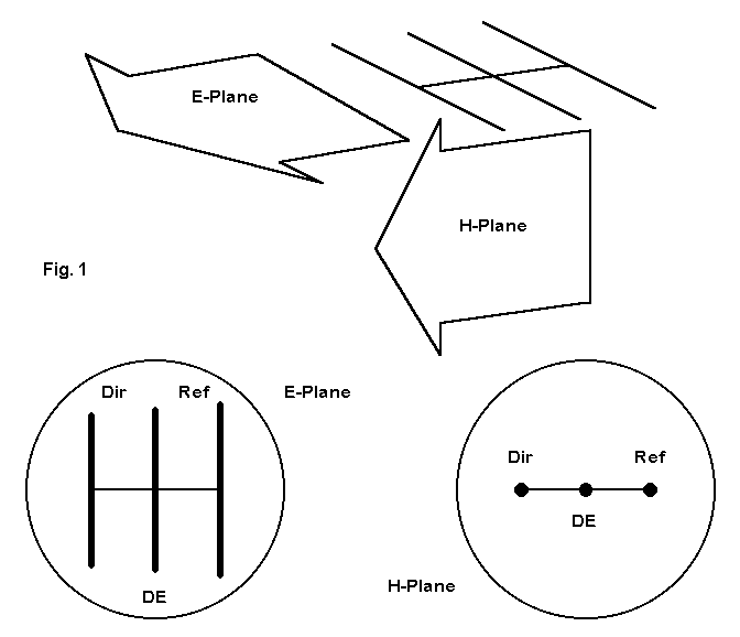
Unless an antenna is a dot or a sphere, the antenna will have identifiable planes of radiation. The traditional names for these planes are the E-plane (associated with the antenna's electrical field) and the H-plane (associated with the antenna's magnetic field). Consider Fig. 1 at the top of the next page. For the Yagi antenna--a very planar antenna--the E-plane is in line with the elements. The H-plane is at right angles to the elements. The fields can use arrow heads to indicate direction a. because the antenna is very directional and b. because the elements define a major plane.
Except for element and object coupling, the magnetic field is far less important to antenna performance at a distance than the electrical field.
Although we shall return to the magnetic antenna field or H-plane before we are done, let's focus on the E-plane or the electrical field of the antenna. This is the field primarily responsible for long distance communications (although one field could not exist without the presence of the other at the antenna).
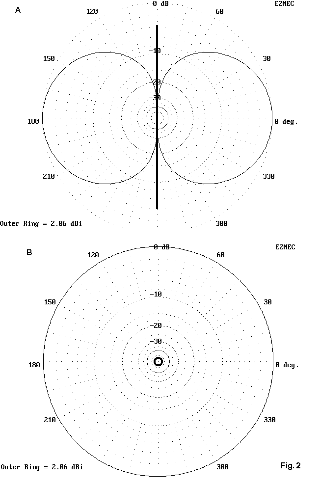
A simple antenna, like a dipole, has many possible E-planes. In Fig. 2 below, the left figure shows the shape of any one of them, since it cuts a cross section in a plane with the element. The right figure looks at the element from the end and sees an indefinitely large number of cross-sections or E-plane figures we might make--all just alike. So if we tilt the left figure progressively upward, it will turn into the right figure-- and vice versa.
To see the transition, look at Fig. 3, a 3-D representation of the same patterns.
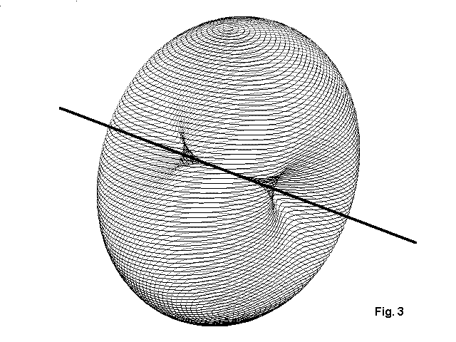
The antenna is exaggerated immensely to shows its orientation relative to the field pattern. However, these fields are represented at arbitrarily huge distances from the antenna, so that if I drew the antenna to scale, it would be invisibly small.
The familiar donut shape pattern can only materialize in free space. If we place any objects of significant size anywhere in the field, some radiation will reflect from them or refract around them, distorting the pattern and at least taking a bite from the donut. With all antennas we use--except in outer space, perhaps--we live with reflections and refractions and distorted patterns. In fact, we have learned to make use of the distortions to make our antennas to a better job of placing radiation fields where we need them.
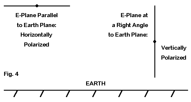
Until further notice, we shall concern ourselves only with the E-plane fields of antennas. If we think E-plane only, then we can understand why we call antennas vertically and horizontally polarized--or vertical and horizontal for short. All we have to do is to bring them down to earth, as we do in Fig. 4. Now we have a reference plane, namely the surface of the earth, against which to compare the E-plane fields of an antenna. If those fields are parallel to the earth's surface, the antenna is horizontally polarized. If the fields are at right angles to the earth's plane, then they are vertically polarized.
The scheme is so simple that you would think that no one could confuse it. However, antennas themselves give us good reason to get confused sometimes. In the real world, hardly any antennas are purely vertical or purely horizontal. Instead, even antennas that we think of a purely one or the other have some remnant (E- plane) radiation of the opposite polarity. Fig. 5 provides a couple of samples.
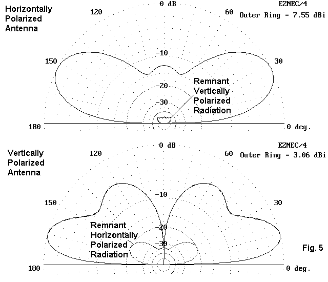
The top antenna is a horizontal dipole. As purely horizontal as we like to think of the dipole, it retain a tiny vertically polarized component, mostly caused by ground reflections which interact with the element. The amount is insignificant in terms of having any affect on the overall antenna pattern. The horizontally polarized field is not distinguishable from the total antenna field.
The bottom antenna happens to be a half-square, which has a larger horizontally polarized radiation component to go with the predominantly vertically polarized radiation. The remnant does have a small but determinant affect on the overall antenna pattern, as evidenced by the slight smudge in the larger pattern outline: the total field and the vertically polarized field are not absolutely coincident.
So when we call an antenna a vertical, what are we saying? We are simply noting that the dominant orientation of the electrical fields from the antenna are at right angles to the earth's surface. Nothing more, nothing less.
There is a myth that says inherently verticals are inferior to horizontals. Consequently, they are always the last option, perhaps when you are faced with using a vertical or not using any antenna at all. although there is a way in which we can give this claim some truth, in fact it is not event a half truth--more like about an 8th truth at best.
Verticals have their best use when we define some total communications picture. Then their use makes eminent sense. So let's construct some communications scenarios.
1. From lower HF down through VLF, the surface wave component of an antenna's radiation is important. From lower HF on up, the surface wave is too weak and dissipates too soon for more than community communications. In the AM broadcast band, a surface wave can cover a radius of 50 miles with modest power (relative to broadcast powers). At VLF, with enough power, a surface wave will go around the world.
Surface waves are most efficient when vertically polarized. Hence, AM broadcast antennas are vertical to enhance their surface wave propagation.
2. Mobile antennas from HF through UHF are vertical for two major reasons. First, moving objects, like cars and boats, do not have much surface area to support horizontal antennas. (The 6 and 2 meter halos are exceptions.) Second, vertical antennas tend to be omnidirectional. For local communications, where a vehicle may undergo many changes of orientation, the vertical means a more even signal strength relative to the other terminal of the path. In most cases of local communications, we are using ground wave, but not the surface wave subdivision. Instead, we are using point- to-point communications.
The other terminal within this local communications ring employs an antenna which offers the highest promise of maximum signal strength. In point-to-point communications, signal polarity is largely sustained along the path. Some polarity skewing occurs because of signal refraction from objects, but not in the main. Hence, to avoid the signal path loss occasioned by cross polarization--which can run from 3 to 20 dB, depending on circumstances--the other terminal uses a vertical antenna as well.
3. Skywave propagation results in polarization skewing, thus voiding in large (but not total) measure the polarization differences between vertical and horizontal antennas. However, some operations dictate that they be able to receive from and transmit to all directions equally well and simultaneously. Since vertical antennas (but not necessarily vertical arrays) are omnidirectional, they are often the only antennas suited to the communications need.
4. In the war between vertical and horizontal antennas, most horizontally polarized antennas do not have an elevation angle of maximum radiation that is low enough to match long distance propagation angles until those antennas are at least 1/2 wl up--or higher. Above that height, going horizontal is seldom a bad choice, but below that height, long-distance communications may suffer with a horizontally polarized antenna. Vertically polarized antennas at or near ground level (as well as those mounted some distance above the ground) inherently have low elevation angles of maximum radiation.
Every installation has its own special concerns that determine the maximum height (and horizontal spread) for antennas. Since 1/2 wl at 40 meters is about 70' and 135' at 80 meters and 275' at 160 meters, achievement of significant radiation at low elevation angles is often impossible for feasible horizontal antennas. Hence, the vertical antenna becomes the antenna of choice.
5. Some installations lack the horizontal space needed to handle a horizontally polarized antenna. In such cases, a vertical antenna with compact horizontal dimensions may be the only feasible antenna.
This last case may be the only one in which one should think that they are using second best. However, it is likely much more productive to devote one's thinking to improving the vertical installation to make it the most effective possible. The items in our list are all very good reasons for using verticals. Although the list is not complete, you can fill in the rest of the possible entries yourself.
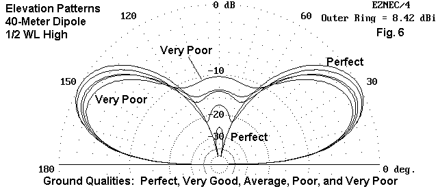
We can illustrate the complexity by a simple demonstration. Fig. 6 shows a series of elevation patterns along the main axis of radiation from a horizontal dipole placed 1/2 wl above ground. The horizontal antenna is concerned with ground quality mostly at a distance from the antenna--the region sometimes called the Fresnel region at several wavelength distance from the antenna. Here, the ground quality has an affect on the reflection of radiation to combine with the direct radiation to form the main elevated beam. Note that from perfect to very poor ground, the increments of signal strength change are quite small and very regular. They progress downward from perfect to very poor in neat steps.

Fig. 7 shows a vertical dipole that begins 10' off the ground and is 1/2 wl long. If we could have perfect ground, the antenna would provide very significant gain. Salt water (not illustrated here because it would bring tears to the eyes of most land-locked vertical users) approximates the perfect pattern quite closely. However, over typical soils, the skywave signal strength is reduced considerably from its ideal. Notice also that the changes are not as regular as with the horizontal antenna. Poor soil produces a slightly stronger skywave signal than does the supposedly better average soil.2 This phenomenon does not occur at every height at which we might mount the vertical.
Because verticals--whether or not they are self- contained or use ground planes--are so interactive with soils, we must acquaint ourselves with soil behavior and peculiarities. For example, at lower HF, RF penetrates the soil much deeper than at upper HF. Since soils are very often layered, with each layer having difference conductivity properties, we may not be able to predict or to model with precision the performance of a vertical antenna at 80 meters, although the same antenna at 20 meters might be very predictable. Likewise, some soils- -such as those in desert areas with sandy salts--may change with the weather--becoming more conductive for a while after a ran storm--the performance of a vertical may change from day to day.3
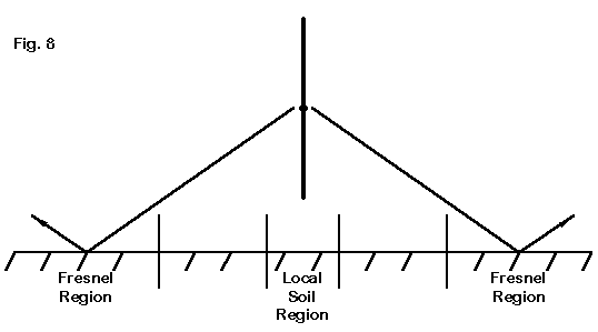
Even though some vertical designs--those we shall eventually classify as self-contained--are dependent for the most part only on soils in the Fresnel region, vertical monopoles that use ground planes are also dependent upon soils immediately beneath the antenna.4 Hence, we must not only concern ourselves with general soil properties, but as well, we must be able to distinguish between local and distant soils, as sketched roughly in Fig. 8.
As complex a subject as soil is when juxtaposed with antennas, the major hindrance to the understanding of vertical antenna behavior are the partial truths that parade as universal generalizations. Here are a few, given without much comment:
1. Verticals always need a ground plane. Wrong.
2. Verticals are omnidirectional. Not all are.
3. Verticals are always weaker than horizontals. Not always, and it depends at which elevation angles you look. Besides, the stronger reception might be mostly noise.
4. A short vertical is next to useless. Very wrong.
5. If you cannot put down a large ground plane, you had better add lots of copper sulphate to your yard soil. Only if you are seeking to kill the grass.
6. Verticals are dangerous to other people in the area. Actually, this can be true, if one installs the antenna carelessly, without due attention to safety. We could spend an entire hour on the subject of differentiating RF exposure (usually not a problem, especially at QRP levels) from RF contact (and the inevitable RF burn). It is the latter that forms the chief danger to folks in the area, but preventing contact is a simple matter to fix by any of a dozen different techniques, ranging from fencing beyond touching range to elevating the antenna out of reach.
7. Every vertical needs a counterpoise. A what?? Let's spend a few moments on this term.
There is nothing in the world of antennas that corresponds to the dead weight facet of the concept of a counterpoise. Every part of an antenna contributes to the antenna far field pattern (except those parts that we specifically design to have self-cancelling radiation). Hence, there is no such thing as a mere counterpoise. We should do our best to expunge the term from the language of antennas.
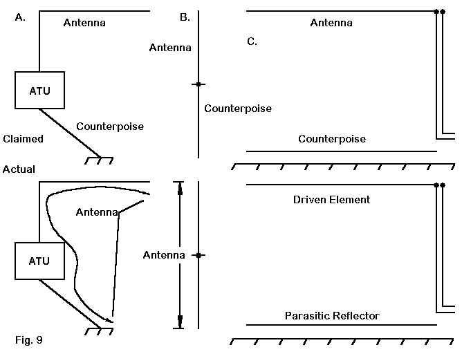
Fig. 9 illustrates three recent applications of the term in ham literature.
Case A involves a wire running for some specified number of feet from the ground terminal of an antenna tuner to ground. However, The entire length of wire from ground to the far elevated end is the antenna, with the feedpoint at the ATU simply off center.
Case B. treats the lower wire from a 1/4 wl vertical as a counterpoise, even though--in its vertical position--it constitutes the other half of a common vertical dipole.
The third case (C) is a modern adaptation of a very old scheme of running a second wire at or near the ground under a horizontal wire, ostensibly to improve some mysterious relationship between the upper wire and the earth. Actually, the horizontal antenna performance remains unchanged, and the wire becomes a trip for anyone careless enough to walk through it. At best, it serves as a parasitic reflector, possibly converting a general purpose antenna into an NVIS (Near Vertical Incidence Skywave) special.
In every case, the so-called counterpoise can be analyzed (and modeled) as a part of the antenna. Hence, let us simply set the term aside as one we no longer need and replace it with specific terms that correctly identify the parts of antennas.
The question is not difficult if the antenna wire is 1/4 wl long or shorter. A quarter wavelength wire fed at its end in free space presents an impossible situation that has no resemblance to a real antenna, like one we might stick in the ground. It always wants some form of completion, whether as a real or a simulated ground plane, so that we can feed it at or near a current maximum.
The problem that boggles our minds is when the vertical antenna element is longer than 1/4 wl. We can in fact have vertical monopoles that are anywhere from 1/4 wl to at least 5/8 wl long. We can also have vertical dipoles that range from short (1/3 wl to 3/8 wl long) to well over the standard 1/2 wl length.
The way to figure out which is which lies in the feedpoint and system: where are you feeding the antenna and how. As to positions, we have roughly two choices. We can feed the antenna at the lower end or we can feed it in the middle. (The upper end is theoretically available as a feedpoint, but somewhat inconvenient except in some nearly vertical sloper designs.)
Our choices as to the method of feed are also a pair. We can feed the antenna at a point at or near a current maximum. We may also feed the antenna at a voltage maximum. We are accustomed to matching a high- current, low voltage, low impedance source to a low impedance antenna feedpoint. We think of such points as the base of a vertical monopole or the center or near center of a dipole. Voltage feeding involves the use of high-Q tank circuits with the power coupled in and the antenna attached at or near the "hot" end of the tank.
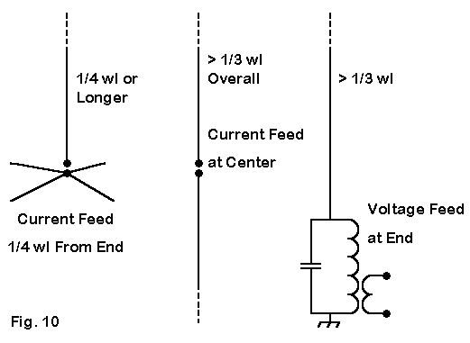
It is sometimes easier to make out the antenna type by analyzing the feed from the bottom rather than the top. In the left example in Fig. 10, the feedpoint is 1/4 wl from the end of the radial. If the remainder of the antenna is also 1/4 wl long, then the feed is similar to that of a dipole, with a lower impedance since the radiation from the radials is self-cancelling. If the vertical portion is longer than 1/4 wl, then the antenna operates similarly to an off-center-fed wire. The feedpoint remains a current feed, although one should watch out for current imbalance on the feeder. Although the vertical part of the antenna, when separated from the radials, is an unbalanced monopole, when the radials are reconnected, balance is restored for a current feed.
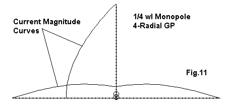
The sketch in Fig. 11, shows the current magnitude along both the vertical and each of the (4) radials for a sample 1/4 wl monopole with ground plane. The current in the radials at the junction is 0.25 of the source value of 1.0. Note the current peaks in the radials near the junction of elements.
The middle case of Fig. 10 is clear enough on its own. The antenna is current fed for lengths between 1/3 wl and nearly 3/4 wl. Because the antenna is balanced about a current maximum at its center, it requires no ground radials to establish that balance.
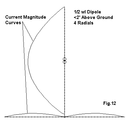
In the model sketched in Fig. 12, the 1/2 wl antenna has been placed over a system of 4 radials, each 1/4 wl long. The current magnitude curves reveal that the current in each radial never rises above 0.1 of the current at the antenna source (1.0), and the current peaks about mid-way down each radial. The gain difference between this little model, with the antenna about 2' above the radial system, is less than 0.25 dB relative to the same antenna in the same position, but with no radial system.
The last case in Fig. 10 strikes many as similar to the first, since the feedpoint is at the base. However, the tank circuit makes this a voltage-fed antenna, and the current maximum is at roughly the center of the antenna. For proper operation, the antenna requires no radials, but does demand a good RF ground return to the source. If we do lay down a radial system, it is not for propagation, but for the enhancement of the RF ground of the tank circuit. Of course, the link for the low- impedance feeder system could be replaced by a tap on the main coil.
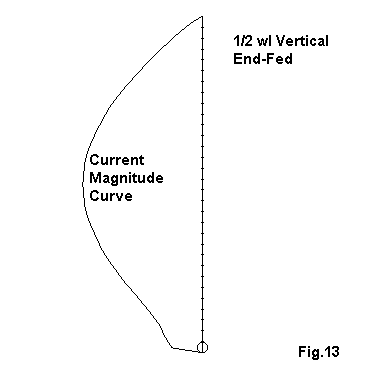
With the end of a 1/2 wl antenna at the same position above ground as the model used in Fig. 12, the antenna shows the same gain, within about 0.1 dB, as the center fed version. Fig. 13 shows the current magnitude distribution along the element, with its peak at the center of the antenna, almost identically to the magnitude pattern of the center-fed version. As an end fed antenna, the feedpoint impedance is high: about 1400 Ohms resistance and 4000 Ohms reactance. However, before we leave our 1/2 wl vertical, let's perform one more experiment.
Compare the current magnitude curves of Fig. 13 and Fig. 14 below. Shape is more important than absolute value of the maximum shown.
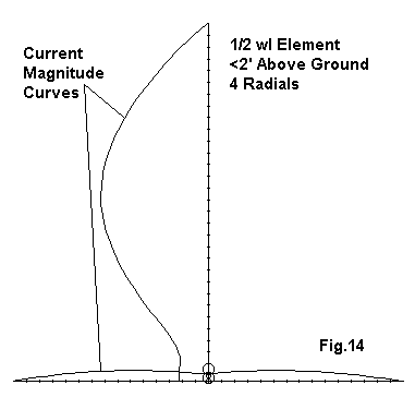
In Fig. 14, the 1/2 wl element was placed above 4 radials and fed against them. The result was similar to that of the 1/2 wl center-fed element placed above the same radial set. Gain differences are less than 0.1 dB, and the maximum current region remains at the element center. The source impedance is high, and the current in the radials reaches about 0.1 of the value at the vertical element center.
This exercise is not designed to show that radials do not help, since we used only 4. However, it does demonstrate that the end-fed 1/2 wl element remains exactly what it is whether or not placed above and fed against radials.
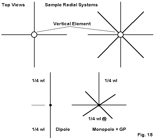
Let's first treat the "plane" part of the phrase. As revealed in Fig. 15, the typical plane consists of a symmetrical arrangement of spokes extending from one side of the feedpoint, where the other side is essentially a vertical element. For the common 1/4 wl vertical antenna, the plane spokes are also approximately 1/4 wl long. Almost any number of spokes may be used so long as we arrange them symmetrically.
The lower half of Fig. 15 shows the function of the plane: to replace the radiating lower half of a vertical dipole with a structure that 1. lets the assembly be resonant on some desired frequency, 2. permits the feedpoint at the element-plane junction to be a current- feed point, and 3. eliminates radiation from the plane by cancellation. That is, radiation from one plane spoke is cancelled by radiation from one or more spokes in the assembly. (Hence, we may in fact use an odd number of radial spokes to make up the plane, and as few as three will preserve the circular vertical pattern that we prize.
Notice that this description of the plane makes no reference to ground. In fact, one can model the antenna just described in free space with no theoretical problems rearing their troublesome heads. A ground-plane vertical requires no ground to operate perfectly well.5
There are actually a large number of subquestions concerning the radial plane of a vertical monopole. Let's look at them, one at a time.
a. How many radials do I need to achieve maximum performance from my vertical + plane? The answer to that question depends on the proximity of the antenna to the earth. The closer to the earth-- including being in the earth, the more radials are needed.
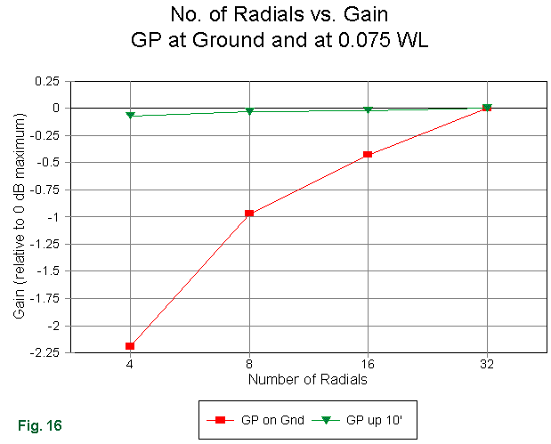
However, it is not very far above the earth that the use of many radials instead of a few fails to help the antenna. As shown in Fig. 16, at a height of 10' (about 0.07 wl at 7 MHz) for the base of a vertical + radial plane, performance is not enhanced by doubling the number of radials up to 32 from an initial set of 4. When those radials lay on the earth, as in the lower curve, performance increases continuously with each doubly of the number of radials. And it would continue to improve up to at least 120 radials. (Because there is some question about the accuracy of absolute value values yielded by NEC models for planes near the ground, but not about the accuracy of performance trends, the graph uses the gain with 32 radials as a reference in both cases, showing the lesser gain with fewer radials. 0 dB is an arbitrary reference point.)6
To the graphed gain, we can also add data concerning the feedpoint impedance as we change the number of radials. For the elevated antenna, source impedance changes by less than 1 Ohm across the range of radials. With surface radials, the impedance changes considerable, with a resistive component variation of 24 Ohms and a reactance variation of 65 Ohms. Hence, the received wisdom for earthed radials holds good: the more radials, the better up to about 120, with about 30 being the minimum number for a long-term, serious installation. For an elevated system, whether on a pole,tower, or roof, 4 to 8 is enough.
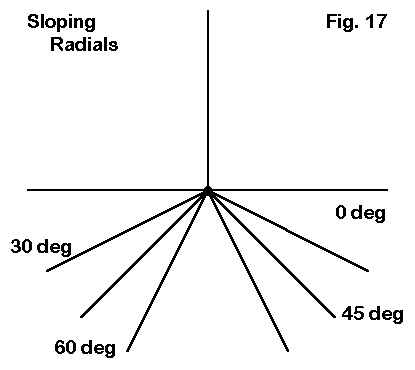
b. What difference, if any, does sloping the radials make to the installation? Fig 17 shows several degrees of sloping we might typically use.
The sloping-radial question implies an elevated vertical because it is difficult to slope 160-meter radials at a 45-degree angle into most kinds of ground. The answer involves two aspects of antenna performance: the gain and the feedpoint impedance. Each answer is partially dependent on the height of the antenna assembly.
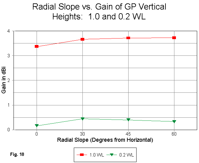
Fig. 18 gives part of the answer in terms of the gain of a 4-radial vertical at two very different heights: 1.0 wl and 0.2 wl. The higher antenna shows a continuous progression of gain increase (although just barely) as the radial angle relative to a flat plane parallel to the earth continues to increase. When sloped, the plane is no longer a purely non-radiating symmetrical system. The horizontally polarized radiation is balanced and self-cancelling. However, the vertically polarized radiation--which grows significantly the greater the slope to the radials--simply adds to the radiation from the upper vertical section. In short, a roof-top vertical with sloping radials is actually a form of vertical dipole.
0.2 wl for the vertical feedpoint is about the lowest height for this modeling test, because at lower heights, the radials drag the ground. However, the approach of the radial ends toward the ground with steeper slopes actually produces less gain than the max gain angle of 30 degrees.
Not only does the gain change with the degree of radial slope, but so too do the elevation angles of maximum radiation (TO or take-off angles) and, of course, the source or feedpoint impedance. The following small table makes the changes clear.
Radial		TO		Feedpoint Z
Slopes		angle		(Resistance)
degrees		degrees		Ohms
Height:  1 wl
 0		26		21.3
30		27		41.3
45		28		49.7
60		28		55.9
Height:  0.2 wl
 0		15		19.4
30		17		43.1
45		18		56.3
60		18		68.6
Evident is the more rapid rise in the source resistance as the radial slope angle increases for the antenna whose radials more closely approach the earth. At a slope of 60 degrees, the 0.2 wl base height of a 40-meter version of this antenna places the radial tips within 2' of the ground with significant vertically polarized radiation from the lower portion of the antenna.
Equally evident is the small but definite increase in take-off angle as the radials approach the position where the antenna would become a vertical dipole. This latter phenomenon occurs because the growing vertically polarized radiation from the bottom wires comes from a position that is lower than the upper wire, and this portion of the radiation has a higher take-off angle. The overall elevation angle of maximum radiation is a composite of the two angles.
c. What differences, if any, does absolute height of the antenna base make to performance? We can only provide a sample modeling test for this question, so the answer will only be partial. However, the results reveal an interesting facet of vertical antenna operation. I placed 40-meter vertical antennas at base heights of 10, 20, and 30 feet. (Base height refers to the lowest extent of the antenna wire or wires.) I used both a vertical monopole with an 8-wire radial system and a full-size vertical dipole. Of course, the top of the dipole was much high (1/4 wl higher, to be more precise). The models for the vertical + radial plane used a plane with no slope, that is, with the radials at right angles to the vertical element.
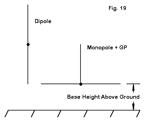
Fig. 19 shows the basic test configuration, with the results in several performance categories tabulated below the figure.
Base Height	Gain	T-O Angle	Feedpoint Resistance
  feet		dBi 	degrees			Ohms
A.  Vertical Dipole
  10		0.22  	16			79.5
  20		0.34  	15			70.8
  30		0.28  	14			68.5
B.  Vertical Monopole with Radial Plane
  10		0.20  	22			26.0
  20		0.27  	18			21.8
  30		0.18  	16			19.8
There is little to choose between any of the antennas or configurations with respect to gain. The maximum gain differential is 0.16 dB. The vertical dipoles exhibit a lower elevation angle of maximum radiation for each height because their feedpoints are always 1/4 wl higher than those of the monopoles in this test. As with all of our test models, the higher the vertical antenna base from the ground, the lower the feedpoint resistance. The low value of the feedpoint resistance may surprise some folks, since we are often told that the inherent resonant resistance at the feedpoint of a vertical monopole is 36 Ohms. It is not. Above about 20' in height, the feedpoint resistance will fluctuate periodically for this antenna between 20 and 22 Ohms. The antenna is modeled with a 2" diameter aluminum tube and 0.25" aluminum radials.7
More significant is the peak gain within each antenna type at the 20' base height. In fact, the peak for the monopole occurs at a slight higher height than 20' and drops more rapidly when the antenna is placed 10' higher. Why the gain exhibits this behavior becomes clear from Fig. 20.
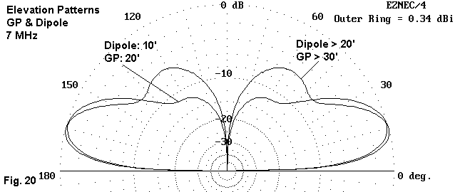
The pattern of a vertical antenna at a low height shows a single lobe when viewed with respect to the field elevation. Notice that the antenna is relatively insensitive to radiation coming from higher elevation angles. As we increase the height of the vertical, a second lobe emerges at a higher elevation angle. This lobe peaks in the vicinity of a 60 degrees elevation angle--too high for the reception of almost anything except atmospheric noise.
Those who use vertical antennas by choice rather than the necessities of a particular antenna site often select them knowing that the gain will not compete with a horizontally polarized antenna they might use instead. However, the signal-to-noise ratio is often improved because atmospherics received from high elevation angles are reduced. Some of that reception advantage disappears if we place the antenna too high. and the second lobe of the elevation pattern achieves full development.
There is a counterweight to this facet of vertical antenna behavior that is especially apt to urban, suburban, and wooded locations. I cannot demonstrate it with a model, but only from the collective experience of many vertical users, including myself. The phenomenon is the dreaded "Rf-eating shrubbery." In the open fields of America's great farming states, a ground-mounted vertical has its best home, with nothing but open fields for many wavelengths in any direction. In crowded locations, the presence of significant structures--both natural and man-made--appears to prevent a ground-mounted vertical from achieving its full performance potential. Therefore, the elevated location of a vertical monopole--for example, a roof-top- -becomes a better location. The higher location is especially apt to the compact, multi-band vertical monopoles produced by many commercial companies.
A second reason for elevating a vertical antenna is the presence of nearby noise sources such as machinery and other instruments that create RF from sparks. Much of this noise is vertically polarized, but hugs the ground in a surface wave. Elevating a vertical can often, but not always, reduce the noise level from these sources. Since noise sources can be very complex, the tactic is not universally successful, but it is worth a try in noisy urban areas.
d. What makes a monopole's radial plane a ground plane? A ground plane, then, is simply the completion of the monopole, in effect making it a dipole with a lower half that yields little or no radiation. It only becomes a ground plane when in close proximity to or contact with the earth itself. As the numerous examples have shown, one effect of contact with the earth is a higher feedpoint impedance value, which most analysts have traditionally interpreted as being the sum of the antenna's natural impedance and something called ground losses.
There may be a better way to think about the ground than as a loss-center. This view gives us no idea of how the losses occur. We think of the ground as a big resistor spread out over some amorphous surface area. The picture, of course, makes no sense whatever.
A better way to think about the earth's surface is as a large area that is a semiconductor. A semiconductor is defined in solid state electronics as a material with neither the high conductivity of the best metals nor the low conductivity of the best insulators. What is in between is a broad territory.
Placing a monopole with a radial plane in the air sets it into a very effective insulating medium. Under these conditions, the fields from the individual radials combine to yield a net of no field at all--assuming a symmetrical radial pattern. If we place the same radial plane in the earth, we cannot talk about fields until we examine all of the conducting material making up the plane. We may insulate the radials, but that does not change anything, except in the local area of the insulation: the radial current yields a field which instantly becomes a current in the adjacent conducting medium. Because soil may be composed of particles, some of which conduct and some of which insulate, the overall situation of a surface radial plane is a mix of fields and currents, both of which are detectable and measurable.
What forms the plane of a vertical monopole when the radials are in the earth is the entire region about the monopole, as suggested in Fig. 21.
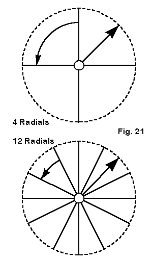
The outline of the region is only a dotted line, because the region has an indefinite boundary. The radial lengths actually show little modeled difference in performance over a 25% change in length, whereas the length of the vertical in air is critical to resonance. Likewise, the lengths of radials that are away from the earth also have a much more marked affect on resonance. Burial of the radials is unnecessary for the earth itself to become part of the plane, since radials very close to the ground show the same effects.
Increasing the number of radials in the earth increases the role of high conductivity material in forming the radial plane of the antenna. This shows up not only as increased gain, but as well in a tighter correlation in the feedpoint impedances between the free space and the at-ground versions of the same structure.
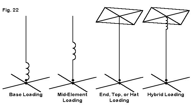
For the 40-meter band down through 160 meters, many of us cannot erect a full-size vertical, even of the quarter wavelength variety. So we look for ways to shorten the antenna. Fig. 22 shows the most common methods: a base-loading inductor, a mid-element loading inductor, a top hat, and a hybrid of inductance and a hot. We shall skip the hybrid, since it should be reserved for mobile use, when the antenna length is super-short.
The loading methods present us with a dilemma. The best method electrically is the most difficult to implement mechanically. Loading coils are fairly straightforward, but the top-loading hat is a heavy wind- catcher. Nonetheless, let's look quickly at some facets of hat loading.
To examine the various loading schemes, I took a full-size 40-meter radial-plane monopole within 0.1' of earth using 16 radials for the test. I then reduced the height to 1/2 full size without changing the radial system. Next, I introduced various loading methods. The base load called for 282.2 Ohms or 6.28 µH. The mid- element load called for 456 Ohms or 10.15 µH. I assumed for the test a Q of 300 as an achievable intermediate range value. The top-hat consisted of 4 0.25" diameter spokes, each 9.1' long. In the table below, the gain is relativized to a value of 0 dB for the full-size monopole, since absolute gain figures for near-earth monopoles have not been fully validated.
Antenna              Relative             TO Angle             Resonant Source
                     Gain dB              degrees              Impedance Ohms
Full-size             0.00                26                   38.8
Base-loaded          -3.03                28                   18.5
Mid-el. load         -1.52                28                   21.3
Hat-loaded           -0.47                27                   24.7
The table should contain no surprises, relative to preconceptions we tend to hold about vertical antennas. However, the difference in relative gain between the base-loaded and the mid-element-loaded monopoles ought to have taken us by surprise. Free space models and models of dipoles using center-loading compared to mid-element loading show far less differential in gain, in fact, too small a differential to make a difference in use. Because mid-element coils have a much higher resistive loss for the same Q, due to the necessity of using larger values of inductive reactance, the overall losses tend to nearly equalize with those of a center-load antenna.
What produces the differential in gain between the base-loaded and the mid-element-loaded monopoles is the proximity of the loading system to the earth and to the right angle plane. Mutual coupling between parts or (or segments of, in models) the main element and the radials differs between the two cases far more than with a linear dipole using center-loading or mid-element- loading inductive reactances. It is thus sound for mobile whips to place loading coils as high as possible.
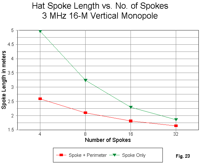
The higher gain and source impedance of the hat-loaded model relative to the other forms of loading is clearly apparent. What is less well understood is that a hat may be composed of any number of spokes and that these spokes may be used alone or with a perimeter wire connecting their tips. Fig. 23 shows the results of a study I did with a 3 MHz monopole and hats of both types. Since the effective length of a spoke + perimeter wire is the length of the spoke plus approximately half the length of the wire connecting two tips, the spoke length of the perimeter system starts and remains shorter than using spokes alone. The two systems converge at about 60 spokes or so, beyond which, the radials simulate a solid disc.
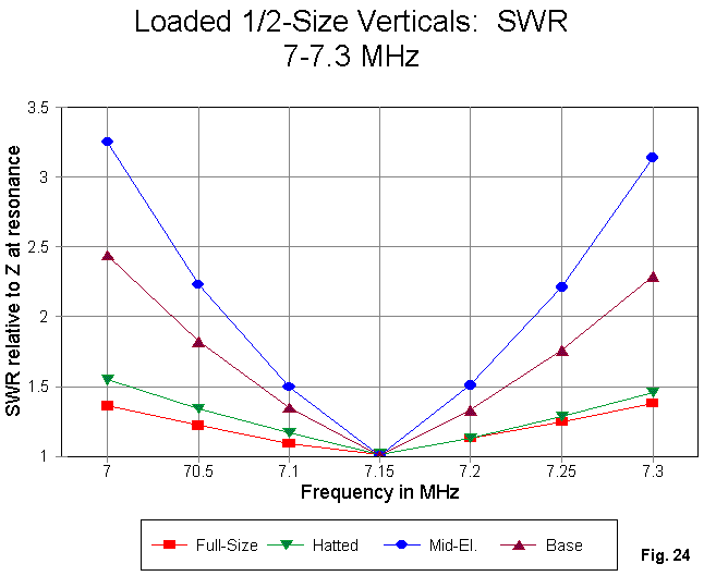
Fig. 24 shows modeled SWR sweeps across 40 meters for the antennas earlier tabulated. Each curve is referenced to the antenna's resonant impedance at 7.15 MHz. Of course, the full-size antenna shows the broadest SWR curve, followed closely and desirably by the curve for the top-hat model.
I have on other occasions already warned you to be ready for surprises, for example, in connection with verticals over different soil types. Here is another case. The narrowest operating bandwidth of the collection occurs with the mid- element-loaded model, not the base-loaded model, despite the reputation of mid-element-loading for providing a wider operating bandwidth than base-loading.
Every radial-plane vertical monopole placed close to or on the earth holds the potential for surprises, including the surprise of working quite well. The worst case of our collection, the base-loaded model, is down by only 3 dB relative to a full size monopole, which amounts to just about 1/2 S-unit.
We encounter similar surprises when analyzing shortened vertical dipoles. We can still obtain very usable performance from a vertical dipole as small as 25% full length. The trick is to minimize losses in both the loading assembly and in the connections associated with low-impedance terminals.
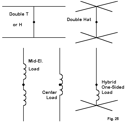
Fig. 25 shows several methods of loading a vertical dipole. Evident are the familiar center and mid-element loading systems that we have already noted. Also at the bottom of the sketch is the Moxon short-radial-plus- reactance system, which has come in for debate. All of these systems are quite usable, even if proponents of various systems cannot fully agree on their relative merits.
The top systems are examples of double hats, one on each end of the dipole, which remains center-fed. Shortening elements by equal amounts at both ends through the use of hats having any number of radials is a tried and true technique for either vertical or horizontal dipoles. It deserves a bit more attention.
As an experiment, I designed a 7 MHz vertical dipole about 1/4 normal length: 17.5' long, composed of 1.25" diameter aluminum, which might be a typical ham installation. The base of the antenna was 4.5' above ground, with the top at 22' up, a workable assembly for most sites. Then, I modeled 4 different ways of loading the antenna:
1. Center loading inductor: 1201 Ohms or 27.3 µH, with a 4-Ohm series resistance for a Q of 300.
2. Mid-element loads at about half-way between the center feedpoint and the ends, each 1096 Ohms or 24.9 µH, with a series resistance of 3.65 Ohms for a Q of 300.
3. Top and bottom hat loads composed of 4 spokes, each 9.35' long, and a perimeter wire, with all aluminum hat assembly wires 0.125" in diameter.
4. Top and bottom "Tee" wires of 0.125" diameter aluminum, each wire 46.6' long.
The results are in the table, with the gain of each antenna version referenced to a value of 0 dB for the double-Tee model.
Antenna              Relative             TO Angle             Feedpoint Z
                     Gain dB              degrees              R +/- jX Ohms
Center load          -2.3                 26                   11.6 - j 0.1
Mid-el. load         -2.1                 26                   18.0 + j 0.1
4-spoke hat          -0.3                 27                   28.2 - j 0.3
Double-Tee            0.0                 27                   26.9 + j 0.4
The inductively loaded versions of the antenna are significantly down in gain from the hatted versions. Most of the loss is in the inductors of finite Q. If truly lossless inductors could be used, the total spread of gain would amount to about 0.5 dB. However, the center- load antenna impedance would be about 7.5 Ohms, while the mid-element-loaded version would be about 18 Ohms. The higher feedpoint impedances shown in the chart reflect the losses in the inductors.
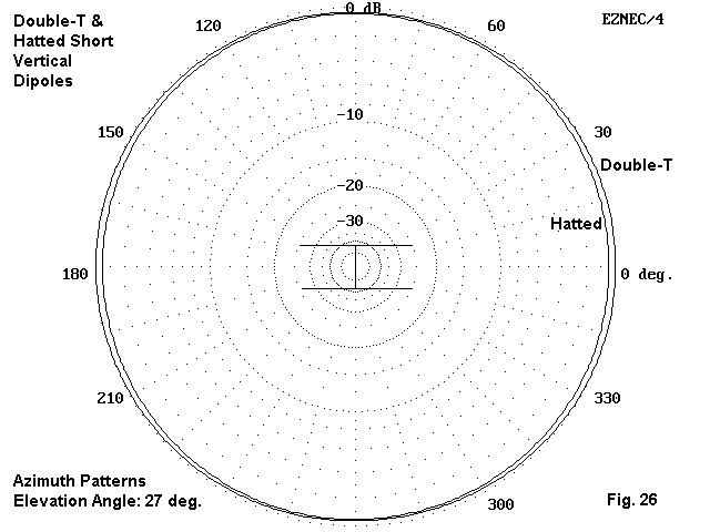
Between the hatted versions there is little to choose except the most convenient installation method for a particular site. As shown in Fig. 26, the gain difference reflects a slight ovalizing of the double-Tee pattern in the direction of the wire ends. (The very slight departure from a circular pattern also shows up in a single Tee monopole over a ground plane. A full 1/4 wl monopole over a 16-radial plane at ground level, incidentally, shows about the same gain and take-off angle as these slightly elevated vertical dipoles.) Other end-loading arrangements are possible. These samples simply demonstrate the feasibility of the technique.
Whatever our initial gain for a single vertical antenna, we can improve upon it by applying standard techniques for creating directional antennas from two or more vertical elements. In the process, we may gain a significant reduction of gain to the rear of the array of elements. In short, we may create vertical beams.
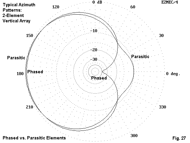
The two most common techniques for creating vertical arrays involve either phasing the current among the elements or using parasitic elements. Fig. 27 shows in a broad way the differences in anticipated performance. Phased elements can deliver a deep null to the rear, often exceeding 30 dB relative to the maximum forward gain. However, the deep phased array null extends only over about 60 degrees of the horizon. The front-to-back ratio of parasitic arrangements rarely exceeds about 10-12 dB. In exchange for accepting a lesser front-to-back ratio, the builder of parasitical arrays has a simpler building task, since phasing techniques require extensive calculations and careful construction.8
A 2-element array gives a broad forward lobe. Even with beam reversal techniques, much of the horizon remains outside of the main lobes. The simplest technique for covering the entire horizon with fixed vertical elements is to use 3 in a triangle and to switch them. Let's briefly examine a full-size and a shortened array of vertical dipoles to see what is involved.
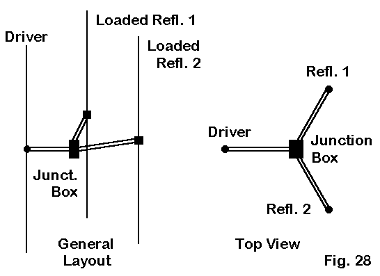
Fig. 28 sketches the outlines of three vertical dipoles set 10' above ground at their bases. For 40 meters, the dipoles ar 65.9' long, and for 30 meters they are 46.3' long. The 40-meter triangle is 22' on a side, while the 30-meter triangle is 15.5' on a side. From each dipole, a 50-Ohm coax stub (RG-213, VF=0.66) extends to a center junction box. The 40-meter stub is 16.4' long, while the 30-meter stub is 11.7' long.
For each direction, one stub is connected to the shack feedline. The other two stubs are shorted to form inductive reactances that electrically lengthen the elements to proper reflector size. A typical switching box is shown in Fig. 29.
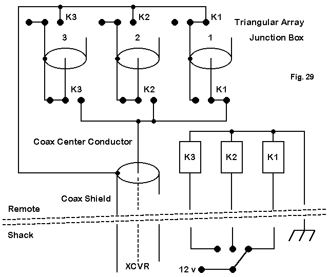
The result is a 3-direction switchable array that can cover the entire horizon, as shown in Fig. 30.
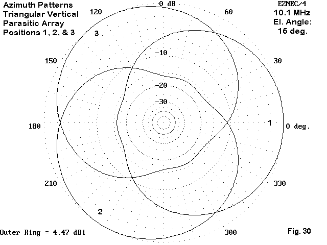
The array gain is about 3 dB greater than a single vertical dipole at the same height. The dual reflector system provides about 12 dB of front-to-back ratio. Although the array is about as simple as one might imagine, its chief drawback is finding supports for the tall vertical dipoles.
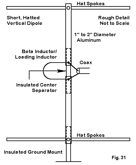
We can also make an array from the short hatted vertical dipoles we briefly examined, using essentially the same 22' per side spacing of elements employed for the full size array. However, the elements can be supported from below, as suggested in Fig. 31. The sketch also hints at another change in arrangements.
The feedpoint impedance for the driven element will be about 25 Ohms. By setting the length of the vertical (or of the hat spokes) a bit short, the driver impedance becomes capacitively reactive. If we introduce a hairpin (a shorted transmission line section) or a coil across the feedpoint, we effect a beta match to bring the impedance to 50ę for coaxial feed.
We leave the beta hairpins or coils across each feedpoint. Using the same switchbox that we used for the full sized array, we switch in a 1/4 wl section of coax from the box to the driver. The 1/4 wl sections from the other elements are shorted at the box, creating an open circuit at the element. The hairpin or coil now become a small inductively reactive load, electrically lengthening the element for reflector service.
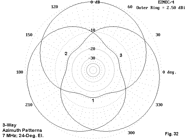
Once more, we can cover the horizon with a 3- position switch. The gain of this short array is about 2.5 to 3 dB over the gain of a single short vertical, with better than 12 dB front-to-back ratio. Although the short array cannot match the forward gain of the much taller vertical array, it can certainly be useful with respect to adding a directional dimension to one's operating.
More complex arrays are certainly possible using 5 elements for a 4-cornered, 3-element parasitic beam system. The center element can be a voltage-fed 1/2 wl tower used to support upper HF beams, with the guy wires used for parasitic elements under proper switching conditions for electrically lengthening and shortening them. In fact, directional vertical arrays for lower HF use are limited only by the electrical and mechanical ingenuity of the builder.
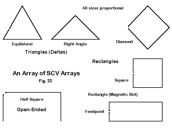
Each of these single loop versions of the SCV produce a bi-directional pattern, ranging from a broad oval for the delta loops to a peanut-shaped pattern for the rectangle and the half square. All of the antennas have a feedpoint 1/4 wl from the top center, which maximizes vertically polarized radiation. The connecting wire between the feedpoint and a point exactly opposite it on the opposing side structure acts as a phasing line by being a 1/2 wl line in which the current phase reverses. The voltage and current at the opposing points are equal in magnitude and opposite in phase, creating a pair of quarter wavelength verticals in phase. Radiation is broadside to the array. The antennas are self-contained and require no ground plane or soil treatment beneath the antenna structure.
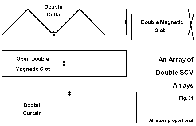
If space permits, the builder can develop "double- wide" version of some SCV configurations for additional gain and directivity, as shown in Fig. 34. Some names originally given to SCV configurations are misnomers. The table below provides a very general indication of relative performance by listing the gains of some common configurations at 7 MHz with a 50' maximum height.
Antenna              Gain          Front-Side           TO Angle             Feed Z
Name                 dBi           Ratio dB             degrees              Z = R Ohms

Equi. Delta          1.5           - 3                  18                   135
R.-A. Delta          1.9           - 5                  20                    60
Dbl R-A Delta        3.7           -12                  20                    40
Sq. Quad             1.6           - 4                  18                   145
Dia. Quad            1.5           - 4                  16                   135
Rect. (MS)           3.0           -12                  17                    15
Dbl MS               3.3           -12                  17                    80
Open DMS             4.5           -25                  16                    30
Half Square          3.4           -15                  18                    65
Bobtail              5.0           -28                  18                    40
In the charted figures, not all of the antennas are at optimal height. Each type of SCV has an optimal height range. Below that range, ground interactions reduce gain significantly; above that range, the gain of the lowest lobe drops as a new higher-angle second lobe forms. Since SCV's are employed to take advantage of the low angle of radiation with rejection of higher-angle QRM and QRN, the secondary lobe actually reduces the desired performance.
Two cautions about SCVs are necessary to get the most from them. First, do not have improper expectations of them. They are capable of gain and directivity relative to a vertical monopole or a vertical dipole. However, that gain is not the gain of a horizontal dipole that is at least 1/2 wl above ground. Instead, because the elevation pattern is typically the low-angle, single lobe pattern associated with monopoles, wise users expect better signal-to-noise ratios from DX signals, but not necessarily a more power signal.
Second, design carefully. Casual design and construction of an SCV may yield disappointment. Besides having a optimal height range, each SCV type also has a optimal shape for maximum gain. In some cases, the ratio of the vertical to horizontal measure may vary with frequency.9
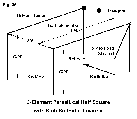
Although any of the basic SCVs is already an array of 2 elements phased, it is fairly straightforward to create a parasitic beam from a pair of SCVs. Fig. 35 shows an example, a 3.6 MHz reversible half-square pair. The length of coax from the reflector is match with a similar line from the driver feedpoint to a center junction box. By switching from direct feed to a short, the line changes from a simple feedline to an inductively reactive shorted stub that electrically lengthens the non- driver to reflector status. Similar schemes can be applied to any of the SCVs to obtain a reversible beam.
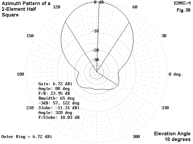
Fig 36 shows the anticipated performance from such a beam when placed at an optimum height above ground. With a forward gain of about 3 dB over a single half square and a worst-case front-to-rear ratio of over 18 dB, the antenna offers excellent low angle (DX) performance for the amateur with the space and supports for the array. This last statement presumes, of course, that we point the antenna in the right directions.
Because SCVs require only wire and accessories, they form an attractive alternative for some locations to erecting complex aluminum structures. For each band, their height requirements are modest compared to the height needed for an equally effective horizontal antenna. On the other hand, we still need some tall trees or structures to hold up the wire.
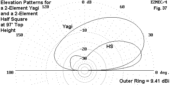
The Yagi has more raw gain, but most of its power is at too high an angle for most DX, since the antenna height is only about 1/3 wl. The half-square beam at the same height promises more power at the lower angle.
More modest installations can expect lesser performance, but similar patterns of performance: better contacts over longer paths and weaker signals closer in. However, even these installations must use careful construction and well-designed structures to achieve all that a vertical can give. For a monopole that is ground- mounted, 4 radials will yield something, but 30 radials will yield a lot more--and 60 or more will yield the most that the antenna can give.
Installation also requires close attention to surroundings. Ground and near-ground mounted verticals tend to be susceptible to signal absorption by ground clutter and to noise from man-made sources. A clear field for at least a wavelength--and hopefully a lot more--is necessary for best results. Moreover, a naturally quiet location is a big help.
For the city and suburban dweller, an elevated mounting may be best, if feasible. A roof top at least 20 to 30 feet up can reduce local noise and improve signal strength on both transmission and reception, especially for multi-band trap verticals. However, if the antenna is a 1/4 wl monopole, one must use a radial system. I personally recommend at least 4 radials for each band (using something like multi-wire flat rotor cable, or similar, or a radial fan of single wire radials spread across the roof) arranged as symmetrically as possible.
Elevated city and suburban installations must give attention to system grounding for lightning and static charge protection, but for most elevated verticals, providing RF isolation from the ground line will prevent diversion of signals into the ground. Simple RF chokes of sturdy construction usually suffice.
Whether circumstance forces us to use a vertical antenna or whether we choose to use one to achieve certain operational goals, the key to successful construction and operation is a better understanding of how verticals work and how various competing vertical possibilities compare in potential. My goal in these notes has been to cut away some outmoded ways of thinking about verticals, including some downright harmful and ignorant ways of talking about them.
Even when approached with thoughtfulness, vertical installations still remain subject to an array of variables that will normally defy precise analysis short of long- term operating experience. Soils that affect far field patterns are often beyond analysis for most ham installations. Some aspects of the operation of ground planes are undergoing re-analysis and re-measurement. In the interim, certain facets of ground planes are vocally disputed, as if loud voices could make the measurements come out as desired. Alas, we must wait patiently for results to emerge before making any final pronouncements--for example, on how Christman elevated radial systems compare with surface ground plane systems.
That does not mean that we cannot learn more about verticals. And it does not mean that we cannot use them effectively. Clear thinking goes a long way to avoiding that dizzying vertigo that has in the past infected the study and use of vertical antennas.

2. The following table may help you appreciate soil differences better. The table represents an adaptation of values found in The ARRL Antenna Book (p. 3-6), which are themselves an adaptation of the table presented by Terman in Radio Engineer's Handbook (p. 709), taken from "Standards of Good Engineering Practice Concerning Standard Broadcast Stations," Federal Register (July 8, 1939), p. 2862. Terman's value for the conductivity of the worst soil listed is an order of magnitude lower than the value shown here.
Soil Description				Conductivity	Permittivity	Relative
 						in S/m 		(Dielectric 	Quality
                        		        	 	Constant)
Fresh water					0.001		80
Salt water					5.0		81
Pastoral, low hills, rich soil, typical from
Dallas, TX, to Lincoln, NE			0.0303		20		Very Good
Pastoral, low hills, rich soil, typical of OH
and IL						0.01		14		Good
Flat country, marshy, densely wooded, typical
of LA near the Mississippi River		0.0075		12
Pastoral, medium hills, and forestation, typical
of MD, PA, NY (exclusive of mountains and
coastline)					0.006		13
Pastoral, medium hills, and forestation, heavy
clay soils, typical of central VA		0.005		13		Average
Rocky soil, steep hills, typically mountainous	0.002		12-14		Poor
Sandy, dry, flat, coastal			0.002		10
Cities, industrial areas			0.001		5		Very Poor
Cities, heavy industrial areas, high buildings	0.001		3		Extremely Poor
3. The best compact treatment of soils and antennas is Chapter 3 of The ARRL Antenna Book.
4. See Antennas and Techniques for Low-Band DXing, by John Devoldere, ON4UN, pages 9-30 to 9-31.
5. Here is a convenient, but neither authoritative nor exhaustive, set of ground types or classifications that may be useful in sorting out various aspects of ones antenna system:
G1. The DC and static discharge ground
G2. Circuitry common buss (ground)
G3. Lightning ground
G4. RF ground
G5. Far field reflective ground
G6. Antenna-completion ground
Only the last type of ground is under discussion, and it does not require THE ground to function. It is in the near field of the antenna, but is not itself the near field ground in the same sense in which we speak of the far field ground. The only time THE ground comes into play is when the antenna-completion ground--or plane--is under, on, or very near THE ground.
6. All models of verticals with ground planes have gone through a thorough development to avoid some modeling pitfalls. They originate with free space dipoles, with their standard 72-Ohm feedpoint impedance. Then, the model replaced the lower leg of the dipole with a set of radials (ranging from 2 through 64 in various steps), in each case, with the radial lengths adjust for resonance. At each step, the models were convergence tested (that is, the number of segments per unit length increased in steps) to establish the internal coherence of the model. Models were also checked to assure that the feedpoint represented as closely as possible the maximum current position on the antenna, with the sum of the adjacent segment currents equal to the source current.
7. The notion that a radial-plane monopole has a feedpoint impedance of 36 Ohms arises from the theoretical exercise of modeling a monopole as a simple vertical element above a perfect ground, thus automatically giving an impedance of 1/2 that of a dipole. In fact, modeling programs will yield the same result, since they create a mathematical image antenna beneath the modeled one. In fact, the source impedance of a real radial-plane monopole varies considerably due to factors not accounted for in the dubious image-antenna calculational convenience. The ratio of diameters of the main element and the radials plays an important role in the feedpoint impedance, as it also does in determining the length of radials for resonance. We obscure these facts with assumptions carried into the field site and also be laying radials and them adjusting the monopole height to achieve resonance. Under these conditions, one rarely if ever achieves maximum current at the feedpoint.
8. The best sources for basic information on phased vertical arrays is The ARRL Antenna Book, Chapter 8, and Low Band DXing, Chapter 11.
9. More complete details on the SCV family of antennas can be found in a series of article appearing in 1998 and 1999 issues of The National Contest Journal. The articles can also be found at this web site.
Updated 5-19-99. © L. B. Cebik, W4RNL. Data may be used for personal purposes, but may not be reproduced for publication in print or any other medium without permission of the author.