 Some Notes on EDZ Beams
The EDZ in its simplest form is a nonresonant wire antenna about 5/4 wavelengths long. Being nonresonant, exact length is noncritical. Shorter versions have smaller side lobes but higher capacitive reactance; longer versions the reverse. Feedpoint impedance ranges from 100 to 150 ohms resistive with well over 600 ohms capacitive reactance. The chief reason for using the EDZ is its 1.5+ dB gain over a dipole comparably situated.
Brian Egan, ZL1LE and I had been discussing EDZ potentials since about 1991. He initially suggested a 2-element beam consisting of an EDZ driven element plus two Yagi-type reflector elements spaced a few feet behind the driven element and each pushed sideways to the wire end limits of the driven element. Modeling this configuration seemed to make a different arrangement preferable. From this arose the 2-element (driven element- reflector) beam noted in the article. The center of each element is inductively loaded, one for matching the feedline, the other for optimizing the rear element as a reflector. With 1/2 wavelength parallel lines down to near ground level, the two matching/loading units could be reversed, reversing the direction of the beam. This installation was tested for a couple of years at W4RNL and worked quite credibly.
Well, folks, as the old song says, "Everything old is new again." Bill McDowell, K4CIA, sent me a copy of an article from the June, 1938, QST, "The Extended Double-Zepp Antenna." In the back pages is a description of how to add a parasitical element to the EDZ. Author Hugo Romander, W2NB, describes a 0.2 wavelength spaced array. The driven element is stub matched to the source feedline. The other element is stub loaded inductively, but at two points: one for use as a reflector, the other for use as a director. Hence, a different system for a reversible beam--and a perfectly competent one. W2NB's system has the advantage of simplicity, while ours has the advantage of convenience. It can be fun to discover that one has reinvented the wheel. Fortunately, the information I added to the end of my article reviewing the principles of stub matching and loading would aid one to replicate the W2NB EDZ beam, so I do not feel totally disconnected from the 1938 work.
From time-to-time, folks discuss the possibilities for a 3-element EDZ beam. Henry Pollock, WB4HFL, is actually planning to build one. The idea led me to try to verify his modeling results and to compare his configuration to an alternative.
As with the 2-element EDZ, one has two main choices of configuration: 3 long elements or a long driven element with pairs of Yagi elements (directors and reflectors) at the extreme limits of the EDZ driving element.
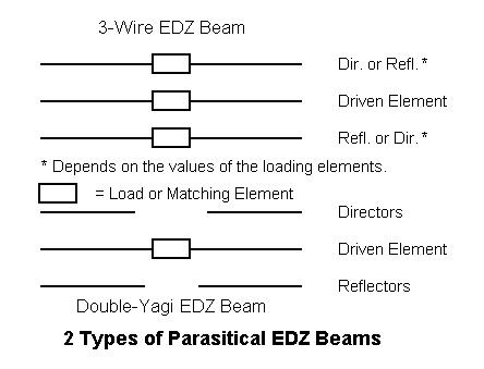
Henry has chosen the double-Yagi version, and very likely wisely so. Since he plans to put it at 60' for 10 meters, let's look at modeling results for both arrangements centered at 28.5 MHz.
The 3-wire EDZ beam can be built from 3 41'8" lengths of #12 wire, each with a center load. The director requires about 800 ohms, the reflector 1150 ohms, and the driven element 980 ohms. The resulting antenna has a resonant feed resistance of about 90-95 ohms, just about right for a 1/4 wl matching section of 70 ohm coax to the regular 50-ohm feedline. You can make the director and reflector inductive loads from coils or from 450-ohm parallel vinyl covered feedline stubs 5.5' and 6.25' long each. If you do not use a split coil for the driven element feed point, you may wish to design a stub matching system--or perhaps use an ATU and parallel line all the way.
The potential beam performance at 60' is quite good: 15.5 dBi gain with about 30 dB front-to-back ratio. Adding the director to our old 2-element EDZ beam really improves the front-to-back ratio more than it helps raw gain.
But here is the rub:

The 3-wire EDZ beam is quite narrow-band in pattern--and even more so in feedpoint impedance and loading. At 28 and 29 MHz, the front-to-back ratio drops to the 7-9 dB range. The feedpoint shows a 250-ohm reactance change across the band. This is a beam that needs adjustment of all 3 elements if one hopes to cover more than 100 kHz of 10 meters. (For lower band versions, narrow the bandwidth in proportion of the ratio of the desired lower frequency to 28.5 MHz.)
The double Yagi EDZ tells a somewhat different story. WB4HFL did not give me detailed dimensions, so I modeled my own version, with directors and reflectors spaced 5' from the driven element. Parasitical elements had outer limits in line with the end of the EDZ element (41'8"). Reflectors were 17'1" and directors were 16'0.5" long. #12 wire, of course, for consistency throughout.
The results at the design center frequency were interesting: 16.0 dBi gain with a front-to-back ratio of 38 dB at 60' height. The front-to-rear quadrants had a minimum ratio of about 21 dB. What the 3-wire gives us in a slightly better front-to-rear ratio at design center is offset by the added gain of the double-Yagi version. Feedpoint impedance of the double Yagi version is about 90 - j1000 ohms, calling for a stub match or an ATU feed system.
However, the WB4HFL-style design has two hidden advantages, partially revealed by a frequency sweep:

First, the double-Yagi version retains a better figure from 28 to 29 MHz, never sinking below 11 dB front-to-back ratio at those extremes. While not superlative, the ratio climbs to nearly 20 dB at the 28.25 and 28.75 marks. These numbers are far superior to the 3-wire beam.
Second, the only adjustment needed across the band is the driven element tuning. Like its counterpart, the double-Yagi version shows a 250-ohm reactance excursion across the band, along with a 75-ohm change in the resistive component. However, parallel feedline and a good ATU would take care of the problem. Because of the high reactance-to-resistance ratio, one might have to carefully select the line length in order to present the ATU with a load it can handle most efficiently. Nonetheless, no other adjustments are necessary, a plus for the double-Yagi design.
Now why does the double-Yagi version work?
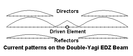
If you look at the current distribution along the EDZ, it consists of a small central peak with outward dips. The outer 1/2 wavelength of the EDZ wire on either side is a perfect dipole current distribution pattern. Parasitical elements aligned with these peaks perform just as they would with independent in-phase separate driven elements. The 3-element double Yagi EDZ beam is actually a form of two in-phase-fed side-by-side 3-element Yagis with 1/4 wavelength tip-to-tip spacing. And the performance is just about the same.
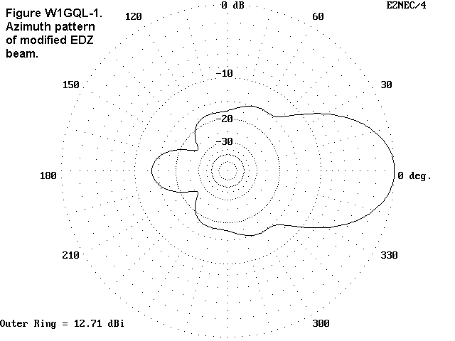
One question that often arises with EDZ beams is how do we get rid of the ears in the pattern, those quartering side lobes. W1GQL, David Billheimer, sent me a design that accomplishes just that--an earless EDZ beam. Figure W1GQL-1 shows the azimuth pattern of this 20-meter 2-element wire beam.
Dave's technique is to create what looks to me like a "gull-wing" design: the driven element is drawn in to midway between the 2 elements, while the parallel sections are drooped like a Vee. See Figure W1GQL-2.
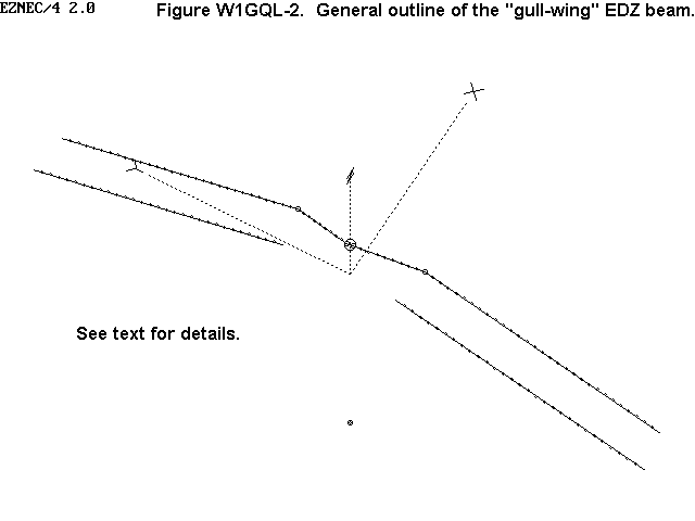
Dave's 20-meter CW beam has a 50' maximum height. The elements are about 5' apart. The two reflectors begin about 14.5' apart and droop to the 33.6' level at a maximum width of 39.4' each side of center. The driven element legs (beginning at center) move outward and forward to a little over 8' each side of center and then parallel the reflectors. (I have rounded the dimension numbers.)
The natural feedpoint of this earless EDZ beam is about 60 ohms resistive and -j1000 ohms reactive. Dave uses stub-tuning to match 50-ohm coax for his narrow-band CW needs. However, the pattern of the beam holds up across 20-meters and can be fed with parallel feedline and an ATU quite effectively.
I have added Dave's beam to demonstrate that we have not yet exhausted all the possibilities with either EDZs or wire beams. Among these notes and two articles, we have look at EDZs, stacked EDZs, parasitical EDZs, bent EDZs, and phased EDZs. I must be overlooking something. . .
Of course: co-linear EDZs.George Goldstone, W8AP, sent me some correspondence he had with Hugo Romander, W2NB (W6CH in the 1960s), and Henry Pollock, WB4HFL, sent me a copy of a Ham Radio article by Alvan Mitchell, W6QVI. The article was an update on Hugo's co-linear EDZ array, which the ARRL Antenna Book of 1943 still carried. Since few folks have access to either Hugo's 1938 article or the 1943 Antenna Book, let's take a look at this version of the EDZ, outlined in the figure below.
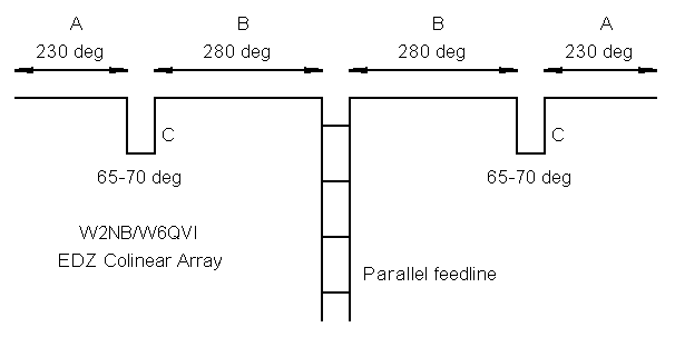
The antenna is given in terms of electrical degrees. The phasing lines are shorted parallel-line stubs. Here are Hugo's 20 meter dimensions and Alvin's 15 meter dimensions as samples: dimensions are in feet.
	Band		A		B		C
	 14		43		53.5		11.5
	 21		27.5		35.5		 7.7
The 15 meter version, which I modeled extensively, is 126' long, about the length of a 75-meter dipole. So what do you get for all that linear space on 15 meters.
You get almost precisely what Hugo predicted in 1938: about 7 dB gain over a dipole similarly place in a bi-directional pattern that is very narrow: 16°-17° between -3 dB points to be as exact as my model will permit. Modeled gain is about 14.3 dBi in a pattern like this one:
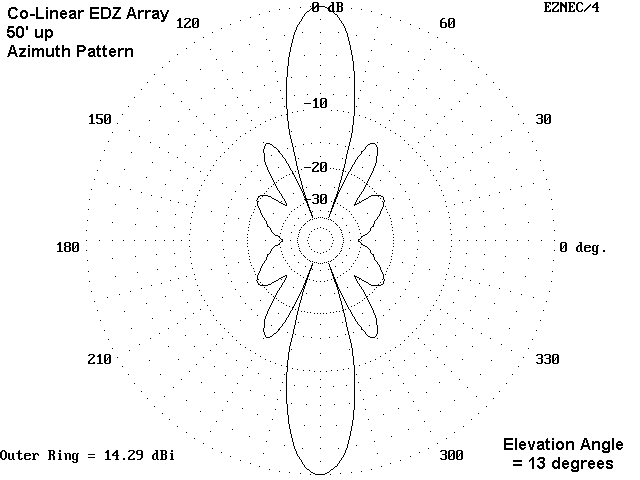
As W2NB pointed out, careful aiming is required. (The EDZ beams earlier noted had beamwidths between 32 and 38 degrees, while a standard Yagi or quad has a beamwidth between 50 and 60 degrees, depending on the number of elements.) This is no antenna for casual world-wide dxing. Rather, it is a serious point-to-point antenna. Within that context, it is an antenna that proves that narrow beamwidths are not impossible at HF. I have expensive flashlights with wider beamwidths.
If you want a bi-directional antenna with a gain of about 18 dBi each way, while retaining the narrow (16-17°) beamwidth, try stacking two of these antennas at 5/8 wl separation. For the 15-meter sample, that places the two at 50' and 79' respectively. The feedpoint impedance, when fed in phase with 450-ohm line at the midpoint between the two, is about 65 + j350 ohms. A pair of series capacitors would cancel the reactance, providing a direct connection to 70-75-ohm cable (through a choke balun).
Let's carry the experiment one step further. To each of the vertically stacked EDZ arrays, one might arrange a series of 1/2 wl reflectors to achieve some further forward gain and reduce the rear lobe. Alternatively, one might place a second vertically stacked array 1/8 wl behind the original vertical stack. Then, feed the rear array with a current magnitude and phase to maximize forward gain and front-to-back ratio. At 21.2 MHz, the spacing would be just about 5.8'. With proper feeding of the rear elements, we might achieve an azimuth pattern like this:

21 dBi forward gain, over 26 dB front-to-back ratio, and a 16-17° beamwidth are figures that amateur radio operators rarely see from antenna arrays whose bases are about 1 wl up and whose tops are 1.7 wl up. Of course, for most operations, such figures are contrary to what is need for effective ham operation, but they might be useful for some specialized operations.
Antennas spaced 1/8 wl apart call for 135° phase differences in the elements on the currents: this is the received wisdom. Unfortunately, it is wrong. Dipoles with this spacing might call for something close to this figure. However, for any two elements spaced more than a small fraction of a wavelength but less than 1/4 wl, there will be for each spacing a relative current magnitude and phase for the rear element that will yield maximum gain and maximum front-to-back ratio, although with real materials, these two maxima may occur on very slightly different frequencies. For the array shown here, the maxima occurred with the rear elements fed at 0.75 the forward element current at a phase angle of 142 degrees. Slightly better performance might have been obtained if the upper and lower phased pairs had been individually optimized.
It is unlikely that standard ZL Special techniques would achieve perfect phasing. Instead, one should most likely use phasing networks to establish the operating conditions. Since the arrays are identical, one could use this method to flip the direction of the beam electronically. "But in the end, this is all hypothetical, isn't it? No one could or would build such an array." Given that all the techniques needed are standard in the field, I am not so sure of this. Some folks might engineer such an array just to say that they have an array with 21 dBi forward gain and to listen to the long-path echoes of their own signals. Hams have done far stranger things in the history of the service. I wonder what might be heard if one of these reversible arrays were aimed directly toward one of the poles.
We are still far from done with the EDZ. I am looking forward to the next step.
These notes are simply the update so far. I'll add more as soon as I learn more about this interesting antenna. If I read enough old articles, I could learn more
very shortly.
Updated 5-10-97 © L. B. Cebik, W4RNL Data may be used for personal purposes, but may not be reproduced for publication in print or any other medium without permission of the author.