
 The Blackboard Jumble
After a few classes, an idea begins to develop: each kind of teaching aid has its own best use. If only I had realized this before my first class, I might have been more effective in getting my students to truly understand the things I take for granted in amateur radio. Even the ubiquitous blackboard that is available in most classrooms (although it is often green today) has its own special strengths in teaching. The jumble of writing crammed into every corner of the surface, with circuit and block diagrams plopped here and there, just has to stop and get organized. But how?
My own experience in 30 years of teaching both ham radio and other subjects suggests that the answer to this question comes in two parts. First, we need a general idea of the best way to use each of the generic types of teaching aids. Just as our wood shops have many different tools, each with its own set of purposes, so too, not every teaching tool is good for every teaching job. Once we understand these basics, then we can begin the main task: to make the blackboard something more than a catch-all for everything that does not seem to have a better home. We shall discover that, despite its reputation for being old-fashioned, the blackboard is an excellent teaching tool for special tasks that none of the more modern teaching aids can do quite as well.
Still, there are at least four general categories of teaching aids we might use in everyday fashion: handouts, overhead transparencies and other preprepared charts, demonstrations, and our old friend, the chalkboard. Each of these has a place in reinforcing lessons and in supplementing the class textbook. Let's take a brief look at each category.
1. Handouts. With easy access to photocopy machines and services and with a computer to invent new collections of ideas, instructors are often tempted to inundate their students with handouts. Too many sheets, however, can be as bad as none at all. The student drowns in a sea of words, overwhelmed rather than enlightened. Reprints, extracts, outlines, and charts--usually handed out at either the beginning or the end of class- -fill the student's notebook. But does the information fill his or her head in a useful way? The object of a handout should be to organize special information, either in class or later.
My own preference (and certainly there is much room for other ways of doing things) is to use handouts for two main purposes: to outline the lesson so that students can follow along and keep their place and to provide special collections of information that organize data in useful ways that our classroom text does not. The idea of a class-organizing outline is fairly straightforward and may include references to the text pages covered, exam questions covered (if relevant), and possibly suggestions for further reading, study, or experimentation. Special collections of data require a word or two more.
| Electrical Phenomenon | Abbrev. | Basic Unit of Measure | Abbrev. | Common Fractional Units |
|---|---|---|---|---|
| Voltage; or electromotive force (e.m.f.); also called Tension or Pressue | E | Volt | V | mV (milliVolts), µV (microVolts) [both common in receiver work]; kV (kiloVolts) [common in power amplifier work and in electrical power transmission line work] |
| Current | I | Ampere (Amp for short) | A | mA (milliAmps), µA (microAmps) [again, both common in receiver and other low power work] |
| Resistance | R | Ohm | Ohm | kOhm (kilOhms), MOhm (MegOhms) [common resistance values in all work] |
| Capacitance | C | Farad | F | µF (microFarads) [power supply, audio, and timing capacitors when in whole numbers; by-pass capacitors when expressed as 0.XX values]; pF (picoFarads) [most common in HF tuned circuits and filters] |
| Inductance | L | Henry | H | mH (milliHenries) [common in audio frequency circuits and some RF chokes]; µH (microHenries) [HF and VHF RF circuits] |
Consider Fig. 1, a partial table of basic electrical phenomena, units of measure, and abbreviations. Anyone can extend and complete this table to the exact degree needed by the students of any particular class, which is one important dimension of handouts: gear them to the exact needs of the students, not to some general parameters of electronics. Different classes, say, for novices and technicians as opposed to extras, may need different information or levels of information.
Handouts are also useful for including important bits of information passed out verbally in the classroom, and they can key a remembrance of explanations. For example, listing the alternative words for voltage might help a student remember that the British like the word "pressure" and thus prevent a confusion if that person reads an R.S.G.B. publication. The student might also remember what is "tense" about a high tension line. In this way, the student begins to draw into a more comprehensive circle the bits and pieces of electrical terminology he or she has met along life's way.
2. Preprepared Charts. Charts that the instructor brings to class, whether on paper or as overhead transparencies, should have a different look than handouts. They have a different purpose, namely, hitting and organizing the critical high points in any body of information. Comparing Fig. 1 and Fig. 2 shows something of the difference in appearance. The transparency has less information on it, but the information it does have stands out in higher relief.
| Electrical Phenomenon | Abbrev. | Basic Unit of Measure | Abbrev. | Common Fractional Units |
|---|---|---|---|---|
| Voltage or electromotive force (e.m.f.) | E | Volt | V | mV, µV, kV |
| Current | I | Ampere | A | mA, µA |
| Resistance | R | Ohm | Ohm | kOhm, MOhm |
| Capacitance | C | Farad | F | µF, pF |
| Inductance | L | Henry | H | mH, µH |
Of course, a good chart or transparency should have lettering large enough for all to see. That is why photocopying book pages onto transparencies often fails to help students in class: they just cannot read the text comfortably. However, computers with bold, large, vivid print fonts let you create truly striking transparency masters.
Moreover, the chart or transparency is never a substitute for the presence and activity of the teacher. Only the teacher can look the students in the eye and see confusions and questions the person is too shy to ask. Also, it takes a teacher to show the students how to navigate a chart or table full of information. As a matter of personal preference, I would use a finished table like Fig. 2 only as a review sheet, not as my primary aid to teaching the information. For that task, I prefer a blackboard (for reasons that will appear in just a few more paragraphs).
For more excellent information on using transparencies, see an earlier volume of this series, The ARRL National Educational Workshop, specifically, 1992. Chester S. Bowles, KD1AP, does an excellent job of providing tips on making and using these charts in his article, "Creating and Using Overhead Transparencies," on pages 21-25.
3. Demonstrations. Demonstrations come in many forms, from showing amateur communications techniques with real equipment to giving students the chance to practice soldering circuits. The keys to effective demonstrations are simplicity and size. First, do not try to cover too many things in one demonstration. Teaching the entire instruction language of Packet on the first demonstration repels rather than attracts future users. Likewise, introducing students to vector calculations of resultant currents in AC-powered circuits with resistance and reactance as their first encounter with Ohm's Law will create more fog than light.
Demonstrations must also be sized to the class. A teacher's desktop demonstration of Ohm's law should not use an AAA battery, 1/8-watt resistor, and a pocket VOM, unless the students can each spend some time peering at the setup, hopefully through a magnifying glass. Demonstrations for the class must be large, so that everyone can see well. Or, they must be rigged for passing around the room or being viewed by each student in turn. Rush no one and be ready to answer every question.
Review past editions of the Workshop proceedings and other instructional aides produced by the League for some excellent ideas on demonstrations. Many, if not most, of the ideas have come from teachers in the field.
4. Blackboards. Is there any work left for the board? The answer is yes. In fact, even if an instructor spends months in preparing his or her ideas, handouts, transparencies, and demonstrations, he or she will spend more time working with the black-, green-, or chalkboard (or the whiteboard with its marker pens) than with all the other teaching aids combined.
The most striking feature about a blackboard is that it begins blank (and hopefully cleanly erased by the preceding user). It is ready for anything, whether or not anticipated. No matter how many calculations you prepare for the class on Ohm's Law or resistors in parallel, someone may ask a question that requires one more example. No matter how complete a chart of schematic diagram symbols you give the class, someone will ask about the one not on the list. There are words you thought everyone knew, until you discover a few students spelling "mho" as "mo." Names and addresses of parts and equipment dealers will inevitably be needed one week prior to their planned introduction into the class. Even if you think that there are better methods for presenting certain information, very often the blackboard is the only handy way.
The other most striking feature about blackboard work is that you create it as you go. The blackboard is an ideal tool for developing ideas and information in a well-calculated progression, one element at a time. With a marker pen and a blank transparency, we can capture some of this special talent on an overhead projector. I have known wheelchair-bound instructors who have successfully taught everything from math to political science this way. But they have all wished they could have a blackboard instead.
The reasons for their blackboard fantasy are two: the position and the eraser. Blackboard writers stand in front of the class and can keep an eye on students to see their responses. Moreover, the chalk eraser corrects errors and permits modifications with the greatest of ease. Combined with some forethought about where on the board to put things and with a sense of neatness to keep material in good order, the blackboard, its chalk, and its eraser provide a tool that permits students to see ideas develop, whether in terms of words, in terms of calculations, or in terms of pictures.
The blackboard, however, cannot substitute for the teacher. Rather, the teacher develops ideas, with the blackboard as his or her developmental partner. Words, together with pictures or writing, provide a reinforced presentation of ideas in the order needed by students for understanding. One of the beauties of the blackboard is that the picture or the writing can precede, follow, or be simultaneous with the talk, according to which order produces the strongest response. There is no general rule here, but experience will gradually give one a sense of the correct order.
To see more clearly what good board use requires and to gain a better appreciation of what blackboards can do for teachers, let's take three examples, one each from the worlds of words, calculations, and diagrams. From these examples will spring all the extrapolations you need to use your board more effectively.
1. Tables of Terms. Fig. 1 and Fig. 2, shown earlier, represent partial views of complete charts of basic electrical terms for Novices and Technicians. Both the handout and the transparency versions had good uses, but neither seems best for the act of teaching the terms themselves in the context of a classroom. One purpose of the exercise is to teach students to avoid confusing the name of the phenomenon and its abbreviation with the name of the unit of measure and its abbreviation. That requires a student to hear and see each type of term used in its own context. That way, each type of term forms the right language linkages for later confident use and recognition.
For this reason, I prefer to develop the table of terms in the figures on the blackboard. The order of development goes something like this:
Step 1. Put the column headings on the board, along with explanations of why the chart requires 5 columns. This task involves distinguishing phenomena from units of measure, with analogies to common measures. For example, length has more than one basic unit of measure (feet or meters), and we might see a blueprint with the notation "L (meaning length) = 3'6" or something similar. When terms are brand new, as they often are for potential hams, this sorting process may be critical for preventing confusions before they occur.
Step 2. Introduce the first term, in this case, voltage or electromotive force. As I explain e.m.f., with some sense of what the phenomena is, I introduce the abbreviation, E, so students will see its connection. Then I add some remarks on tension and pressure so that students can coalesce similar ideas with multiple names under a single heading.
Step 3. Introduce the unit of measure, here the volt. Mentioning Volta and the naming of electronic units (but not many phenomena) after pioneers in the field gives students a handle for distinguishing unit terms from phenomenon terms. Most abbreviations come naturally.
Step 4. Introduce common fractional units, saying something about the contexts in which each might most commonly appear. In this case, each subunit can be explained with or without reference to a complete table of prefixes. Generally, I prefer not to get two tables going at once, since the development of each can interfere with the development of the other.
Repeating the process for each term allows the table to grow on the board. If lessons on the basics of capacitance and inductances occur at a future class, I often prewrite the old elements of the table on the board just before class, leaving room to develop the new ones.
Working with the developing table is just as important as developing it in the first place. Leave it on the board while you proceed to a related topic, perhaps Ohm's Law. Be sure to ask of your voltage source, "What is the voltage?" Someone is bound to answer, "6." That gives you the perfect opportunity to explain that numbers in electronics (excepting Q) require units of measure. In short, thinking developmentally about using the blackboard as an aid to teaching also allows you to unfold other important and related ideas.
2. Calculations. Calculations are a natural for blackboard work. We can put up and erase example after example until students catch on to the idea. Nevertheless, we often do not use the board to full advantage from the teaching point of view. The student needs to understand every little--as well as big--step of a problem. What experience can take for granted and do automatically, teaching cannot. Developing a calculation is not just applying a formula, but as well it is a systematic process of thinking through a problem and reflecting that thinking in an orderly way on the board. Let's assume that we wish to show how to use Ohm's Law with all calculations made in basic units. The development might look like this:
Step 1. Lay out the sample measurements and the quantity we wish to
find. Be consistent with units, either spelling them out or using the
proper abbreviations. For example:
     Measured voltage:   6 V
     Measured current:   3 mA
     Needed:             Resistance in kOhms
Step 2. Since we wish to make the calculation in basic units, that is, using Volts and Amps, we have a conversion step here. Whether we place the conversion next to the current entry or as another line of entry is optional so long as the work is neat and the student can see exactly what needs to be done.
Measured Current: 3 mA = 0.003 A
Step 3. Calculate the resistance in basic units. Until students have
mastered the algebraic transforms of Ohm's Law, place the correct form
ahead of the fairly simple calculation. Then, let the students call out
the answer.
     R = E   /   I
     R = 6 V / 0.003 A
     R = 2000 Ohms
Step 4. Finally, add the conversion step to put the answer in the correct units. Again, it is optional whether you use a new line or add the step to the numerical answer line, so long as students are clear about what you did and why.
R = 2000 Ohms or 2 kOhms
No law requires you to use a vertical scheme for developing classroom calculation, although it does permit alignment of critical elements in the calculation process. Call attention to these alignments to ensure that the student notices them. In other words, take nothing for granted about the naturalness of seeing things in the "common" way. That way is not yet common to most potential hams, but it will become common as a result of your teaching. Thus, it may prove most helpful to students to style your developing calculations to coincide with those the student is likely to see in his or her text and in amateur magazines and books.
Once you have constructed enough calculations on the board, you may wish to provide students with some handouts with others: use worked, partially worked, and unworked samples. You can guide them through the process of finishing or making some of the calculations by labeling lines. To make the handout more effective, instruct the student to use a strip of paper to cover all the lines below the one he or she is reading. He or she should move to the next line only when the current one is fully understood. If understanding eludes the student, there is a question for the next class. Tell the student to mark the item and ask about it at the beginning of the next class.
Many students are inclined to ask these questions in private, because they are embarrassed about not understanding. Unless the student is especially shy, encourage him or her to ask within the class. That way, everyone benefits from the explanation. My experience has taught me two important lessons. First, for everyone who asks a question, there are five others who refrain, even though they need to ask the very same question. Second, the only foolish question is the one unasked. Try to give your classes the sense of community in which everyone helps everyone else. That more than any other technique seems to break the barrier of silence.
Of course, good answers contribute to a student's willingness to ask questions. When you can point to the developing progression of a calculation or a table of ideas to show precisely where something went wrong and how to make it right, you have a key ingredient of some very good answers.
3. Diagrams. Most instructors (including me) tend to draw too fast on the blackboard. The simpler the diagram, the faster we draw. In turn, the faster we draw, the less students learn. Speed makes messy drawings. Even more importantly, speed turns our diagrams into mysteries: instead of clarifying principles, speedy drawings obscure them.
Developmental thinking can change all that. By treating the drawing or schematic diagram as an orderly, emerging set of ideas, we can use it to familiarize students with the crucial elements that go into circuits and systems, all the while relating each step to basic principles, such as Ohm's Law. To see how this works, let's assume that we wish to illustrate Ohm's Law for a Novice class. We shall use a combination of ingredients, each developing the ideas in parallel. First, there is an experiment on the table using batteries or power supplies, some "unknown" resistors (say, 5-watters, with tape over the value markings), a voltmeter, an ammeter (or milliammeter), and an ohmmeter on the side to check our results.
Second, there will be a set of calculations. For this example, we may use the ones just completed. Finally, we shall develop one or more circuit diagrams to help students relate schematic drawings to both real-world components and to the fundamental formulas of electronics. The one thing we shall leave out of this exercise is any sense of hurry.
Even without the calculations and the experiment, the principles of developing diagrams still apply. Adding in the other elements reinforces the importance of letting diagrams emerge rather than just appear as a whole. The sample exercise might look like this:
Step 1. Start by setting up the power source, perhaps a battery. Then, begin the diagram by showing only the battery or power source. We shall follow this procedure at each step so that students can associate components with their schematic representations. Even if we have previously presented a list of schematic symbols and samples of their live counterparts, showing the correspondence in action can augment that past lesson and add to it a new dimension. Here, students will see the connections that make components into circuits.
The first stage of our diagram on the board will thus look like this:
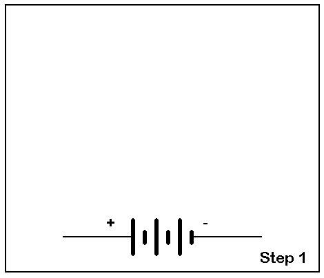
Step 2. Add a switch to both the experiment and the diagram and explain its use. Not only will it make and break current flow for our tests, but it will also contribute to our safety in handling the components. So our diagram grows a bit:

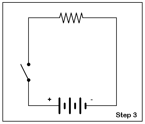
Step 3. Add a resistor to complete the circuit. This addition shows the basic units involved in our prospective calculation, even though we have yet to add the measuring devices.
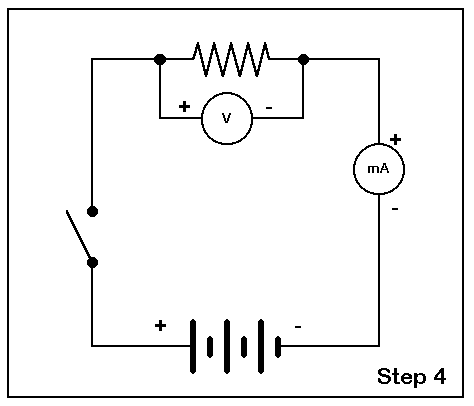
Step 4. If the students understand the basic idea of a complete circuit, we can then show and explain how the meters fit into the overall scheme. Place a meter across the resistor while explaining why voltmeters are used that way. Then interrupt the line near the resistor with a small erasure to insert the (milli)ammeter. It pays to ensure that students understand that current travels through the meter without significant resistance and hence does not materially affect the accuracy of our work.
Step 5. You are now ready to switch on power and make some measurements. With the touch of an eraser and chalk, close the diagramed switch as you turn on the experiment. With the measurements, start the calculation procedure previously outlined. Add the values to the diagram, with the resistor value left open.
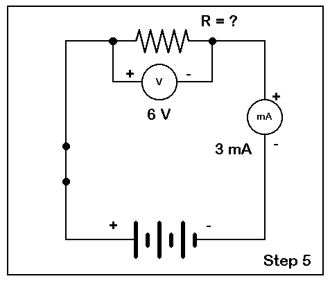
Step 6. Moving through the steps of the calculation, we can arrive at the value of the resistor. To complete the task, we can erase the question mark and replace it with the value of the resistor. Now to check our work.
Step 7. Switch off the power, remove the resistor, and check its value with the ohmmeter. If the resistor was well marked, you can strip the tape to reveal its value. An explanation of tolerances may also be in order. You may even wish to diagram the ohmmeter hook-up.
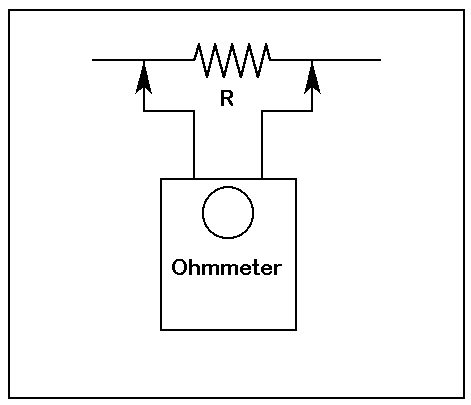
You can now run through a collection of unknown resistors with the ease of placing them into the experimental circuit (with the power off) and going back to a question mark for the resistor value on the diagram. Make a mental note that you owe the students a later explanation of ohmmeters as devices that usually measure current with a preset voltage and only have a scale calibrated in Ohms.
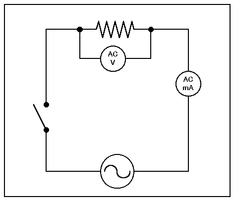
One advantage of developing our very simple diagram so carefully is that we can make changes without creating confusion. Suppose, for instance, we wish to illustrate the fact that Ohm's Law works equally well for DC and AC. In our experiment, we would replace the DC source with an AC source. Ideally, the source would be capable of an R.M.S. voltage that is equal to the voltage of the DC source. Then, students could expect the same current to flow as in the first experiment. We need, of course, meters for AC voltage and current.
Changing our well-developed diagram is as easy as erasing the DC source and plugging in the AC source:
The technique also applies to replacing resistors with capacitors and with inductors to illustrate their ability to limit the flow of alternating current. Note, however, that although we can show the action of DC with a capacitor, if we use a sufficiently large electrolytic to demonstrate turn- on current, we cannot demonstrate the action of an inductor with DC without a current-limiting resistor in the circuit. Blown fuses generally do not make good demonstrations, although with the right preparation (being certain that only fuses will blow in our DC source), they can make a vivid demonstration of DC current through an inductor.
Our look at the steps in the development of even the simplest circuit diagram has been patiently slow for two reasons. First, students need to see diagrams emerge in order to understand every aspect of the circuit they are seeing--often for the first time. Remember, the diagram is for the student, not for the instructor.
Second, every step in the development of a diagram is a teaching opportunity, even if it may seem that the instructor is repeating something already said. The repetition, surrounded by something new to the student, reinforces the earlier lesson by connecting it to additional information and ideas. In this way, the student's understanding grows and develops in ways quite parallel to the development of our charts, our calculations, and our diagrams.
Just as with any set of techniques, there are effective and ineffective ways of applying them. The ineffective way to use a chalkboard developmentally is simply to parrot the procedures mechanically. Or, one can get so wrapped up in replicating the procedure that one's attention is diverted from the students. Good principles become bad ideas if we do not use them wisely.
Making the most of the developmental potential of a blackboard
requires creativity and a bit of a flourish annexed to an understanding of
the principles behind the procedures outlined here. For all the teaching
aids available to us, instruction remains a person-to-person enterprise.
Good procedures plus the best of the teacher's personality tend to make the
best instruction and the best learning. Of course, a little neatness on
the blackboard has never been known to hurt a thing. It is the first step
to avoiding the dreaded blackboard jumble.
From Proceedings of the 1993 National ARRL Education Workshop, (Newington: ARRL, 1993), pp. 27-34 © L. B. Cebik, W4RNL. Data may be used for personal purposes, but may not be reproduced for publication in print or any other medium without permission of the author.