 Multi-Diameter Dipoles: MININEC vs. NEC-4
When modeled in MININEC, no problems with convergence were encountered with reasonable numbers of segments per half-wavelength. However, when modeled with NEC-4, convergence only occurred with very large numbers of segments per half-wavelength. Reducing the diameter of these center sections to that of the immediately adjacent sections eliminated the problem of convergence--that is, convergence occurred with reasonable numbers of segments per half-wavelength.
To explore this anomaly, I set up a small test of systematically modeling dipoles with larger center sections. The test frequency was 14 MHz. The initial material was 0.5" diameter aluminum. In increments of 2 feet each side of center, I increased the length of a larger diameter center section in progressive steps for total lengths of 4, 8, 12, etc. feet up to an including the total antenna length.
Each antenna was resonated to less than 1 ohm reactance. Thus, the length of each model differs. In the graphs that follow, the far right entry labeled "36" is a place holder for the actual total length of the antenna at the increased diameter. Thus, that column alone violates the linear progression of the other enlarged center sections.
Each model was tested using ratios of 2:1, 3:1, and 4:1 relative to the original dipole diameter of 0.5 inches, for center section diameters of 1, 1.5, and 2 inches. All models are free space.
The models were first run in MININEC 3.13 via ELNEC 3. Segmentation was set at 34 segments overall, using 1 segment per foot of enlarged center section, with the remaining segments split between the smaller diameter end sections. This yielded segment lengths that are well within all MININEC boundaries for accurate results, as well as very reasonably close in length between the antenna wires.
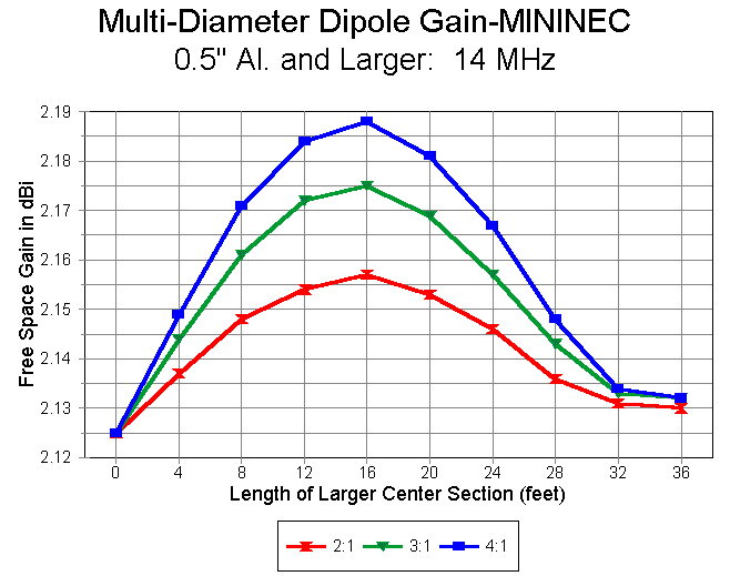
The following graphs shows the progression of gain figures for the MININEC runs. Interestingly, the gain of the models peak when the enlarged center section is just under half the total length of the antenna. As the larger center section is further lengthened, MININEC shows a decrease in gain. The curves for the 3 ratios are nicely congruent.
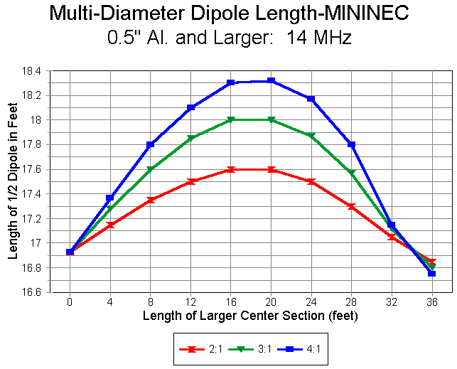
The length of the resonant antenna also changes with the length of the larger-diameter center section. Overall antenna length actually peaks with center-section lengths slightly longer than those for maximum gain, as the following graph demonstrates. MININEC models do not reach a final shortened length associated with fatter elements until the entire antenna is at the larger diameter.
The same antennas were run with NEC-4, initially with EZNEC Pro and later with a beta version of GNEC. Segmentation was virtually the same as with the MININEC models with a single additional segment in the center section to permit the required mid-segment feedpoint. As with the MININEC models, each antenna was resonated within +/- 1 ohm of zero reactance for models using 2:1, 3:1, and 4:1 ratios of the center segment to the end sections.
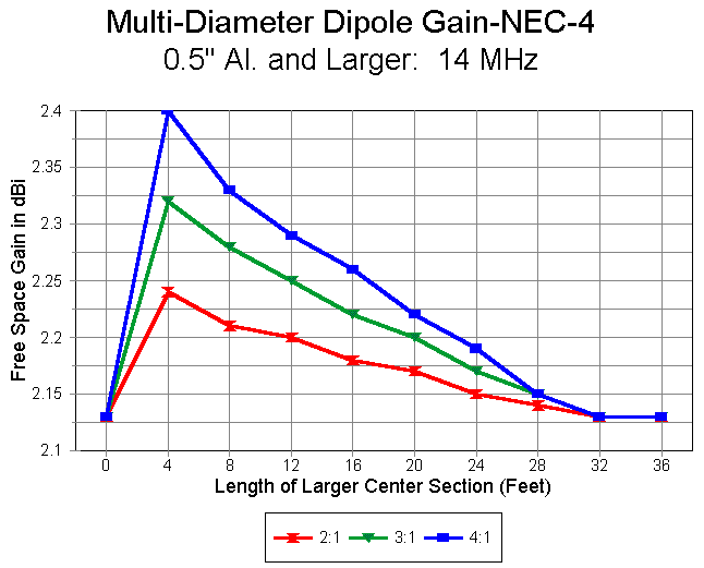
The pattern of gain produced by the NEC-4 models, shown in the following graph, is quite unlike that yielded by MININEC. Maximum gain occurs with the shortest possible larger-diameter center section and progressively decreases as the center section is lengthened. The curves for NEC-4 are less smooth than for MININEC because the former, in the commercial versions noted, yield gain figures to 2 decimal places, while the latter yields figures to 3 decimal places. Hence, NEC-4 rounding yields somewhat stair- step curves. within those limits, the curves for the three different diameter ratios are congruent.
Equally congruent are the overall antenna length curves (shown in terms of lengths each side of the feedpoint in the graphs).
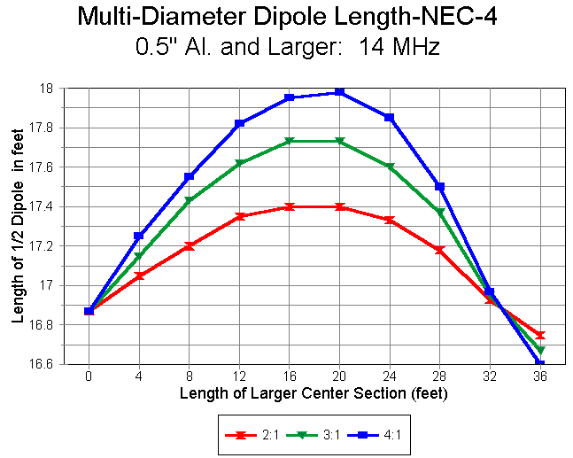
Interestingly, despite the vastly different gain curves, the overall antenna length curves for MININEC and NEC are exceedingly comparable. MININEC yields slightly longer resonant lengths for each modeled case, a phenomenon long noted (and corrected for in some commercial versions of MININEC). Nonetheless, MININEC and NEC-4 show the longest resonant length at just about the same length of larger-diameter center section, as shown in the following graph. This graph uses the 4:1 ratio curves because they produce the sharpest length peaks and would be most sensitive to significant differences in the peak point for each modeling system with these models.
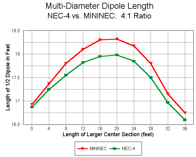
The question that remains is which of the two gain curves is the more reliable. The MININEC gain curves with a 2:1 diameter ratio of center section to end sections were rerun with double the number of sections. Gain figures were convergent within a maximum divergences of 0.003 dB. The comparable NEC-4 models, when segments were doubled (minus 1 to retain an odd number of segments in the wire containing the feedpoint), showed an order of magnitude less convergence with short center sections of 4 and 8 feet. Convergence within the two decimal places occurred only when the center section reached 24 feet long. This result is consistent with the difficulty of converging Yagi models employing short, large-diameter center sections for each element.
Moreover, the NEC-4 curve totally envelopes the MININEC curve, as shown in the following graph for diameter ratios of 2:1. Within the limits of NEC-4 rounding, nowhere does the MININEC curve exceed the NEC-4 curve in gain value. In contrast, for shorter center sections, the reported gain of the NEC-4 model is significantly higher.
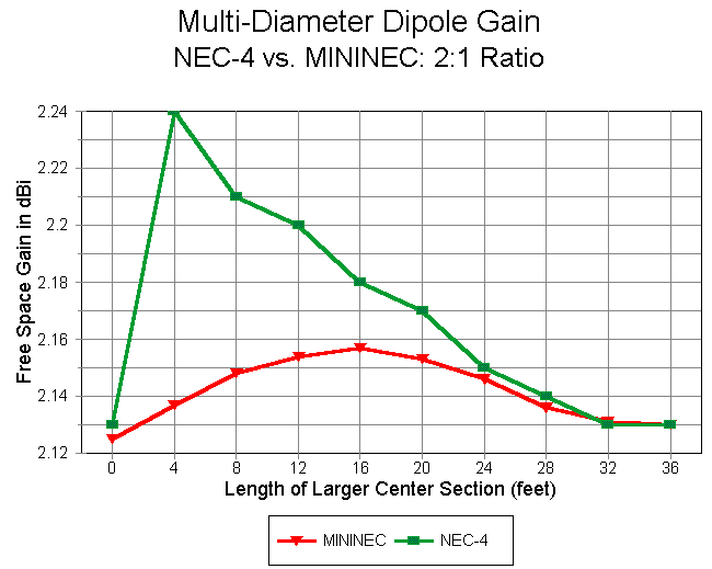
The anomalous results yielded by NEC-4 with shorter, large-diameter center sections of multi-diameter dipoles gains importance as these figures accumulate in multi-element antenna arrays. Since these gains are usually cumulative in most antennas designed for maximum or close to maximum gain, the reported gain may be significantly higher than reality.
The convergence test and the fact that the NEC-4 curve envelopes the MININEC curve are strong indicators that NEC-4 may be simply inaccurate when antenna elements consist of multi-diameter sections such that the center section is short and significantly larger in diameter than succeeding sections of the element. The degree to which such an inaccuracy becomes significant operationally to an antenna design depends on many variables of both design and engineering goal and cannot be independently estimated. Unless independently confirmed as in fact accurate (with MININEC's curves consequently invalidated), the phenomenon will at least be disconcerting to antenna modelers.
Attributing an anomaly to NEC-4 in this case does not itself certify the accuracy of the MININEC result. Even if correct, the increase of gain is of more mathematical interest than operational significance. At a diameter ratio of 4:1, the maximum gain is only about 0.06 dB relative to a dipole of the thinner size.
For those who model antennas, the disparity between the two modeling
programs should at least be noted and accounted for wherever it emerges.
Updated 9-19-97. © L. B. Cebik, W4RNL. Data may be used for personal purposes, but may not be reproduced for publication in print or any other medium without permission of the author.