
 Corner Reflectors Revisited
In the museum of overlooked antennas lies the corner reflector. Once a bastion of TV reception and occasional ham use, this antenna has given way to TV cable and ham Yagis. In the 70 cm band (420-450 MHz), where TV and amateur radio almost meet, the corner reflector had its heyday and has passed largely into history.
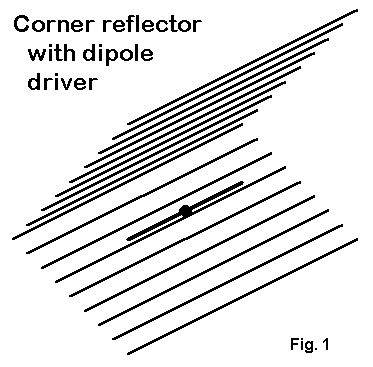
The most common etching of the corner reflector is shown in Fig. 1. When not adapting a TV antenna, most hams used screen wire and frames for the reflector planes.
I recently had occasion to revisit the corner reflector and to model it. One version showed very nice gain from 400-500 MHz, along with a feedpoint impedance that was convertible across the operating range to something close enough to either 50 or 70 Ohms within less than a 2:1 SWR. I began to wonder why the antenna had been discarded.

Part of the answer shows up in Fig. 2. A 10-element DL6WU log-calculated Yagi for 432 MHz appears roughly in scale with an optimized corner reflector of similar performance. The footprints are indeed different. Still we have the nagging question of whether the corner reflector might have something to offer that the Yagi does not. To develop some sort of answer, let's look at each antenna briefly.
The antenna description file for the DL6WU Yagi appears at the end of this part of the story , in case someone wishes to replicate the antenna. The originator is most noted for the logarithmic technique for calculating element lengths and spacings. Modeling can tweak his results, but not by much--and not without ruining some other features of his designs. First, the designs were all geared to a 50-Ohm feedpoint impedance, even if we are shifting to 70-Ohm hardline scrounged from the cable industry. Second, the designs were broadbanded both in source impedance and in overall antenna characteristics. Third, the designs were generated in large models--the original for this 10-element version had 26 elements. At most points down the boom, the home builder could snip off the directors he did not want to build and still have a good Yagi with a 50-Ohm feedpoint impedance.
The antenna description will list the dimensions in inches for direct comparison with the corner reflector. However, the originals are given in millimeters, with 4 mm as the element diameter. The entire array comes in at under 5' long and a maximum width of just over 13" at the reflector.
The corner array we shall look at in some detail is bigger than most amateur source recommend. The dotted lines of Fig. 2 indicate the rough reflector size one commonly sees, but that set of dimensions yields fairly mediocre performance. The larger reflector allows optimizing the array for 432 MHz as a design frequency for maximum gain and very adequate front-to- back ratio.
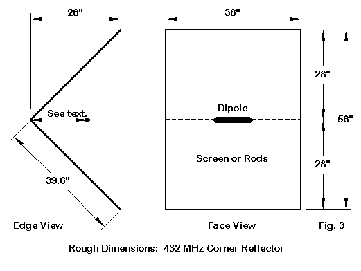
In Fig. 3, we can find dimensions enough to start a building project, although it is wise to supplement this figure with data from the model description file at the end of Part 2 of these notes. Note that the 2 reflector planes are each virtually square. Their dimensions are between 1.4 and 1.45 wl. The design is a standard 90-degree reflector and uses 3/8" (about 8 mm) aluminum tubing. For simplicity, a 3/8" diameter dipole is the driver, although the widest-band corner reflectors use(d) bent Brown-Woodward bow-tie drivers. We shall discuss the driver placement further down this note pad.
Two sets of numbers have emerged regarding corner reflectors: minimums and optimums. Unfortunately, the minimum numbers have received wider distribution among hams, while the more optimal numbers lie buried in Kraus, Antennas, 2nd Ed. (Section 12-3) and his sources. W8JK hold the patent for the corner reflector. Kraus specifies numbers as high as 1.62 wl for rod lengths and 1.5 wl for the length of each reflector plane--not far off the numbers used to develop the model used here. The rod diameters and spacing used here are also well within his limits. We should remember that most of the information on corner reflectors was developed long before modeling software was developed.
The numbers in Fig. 3 reflect the results of modeling with the rod construction. A different type of reflector plane may require adjustment. Preliminary models using wire grid techniques to fill the plane more fully suggest that these planes might need to be slightly larger than the dimensions shown for the rods. It appears that adequate modeling of corner reflectors has just begun.
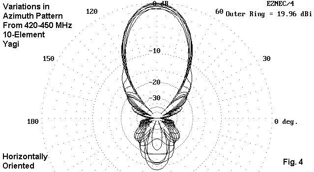
Fig. 4 combines 420-450 MHz (5 MHz increments) azimuth patterns for the Yagi, oriented horizontally, with the antenna 30' (over 13 wl) above average earth, using an elevation angle of 1.1 degrees. Three features of the pattern overlays should call themselves to our attention. First, the front-to-back ratio is highly variable across the band. Second, the gain shows significant variation across the band. Third, the side lobe structure varies considerably as we move from one frequency to the next.
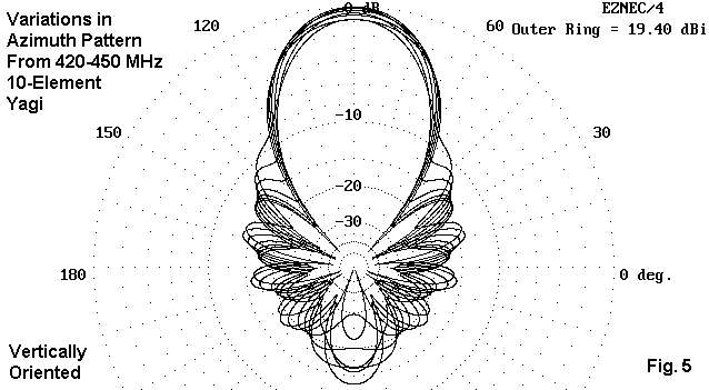
In Fig. 5 we have the same situation, but with the antenna oriented vertically. The side lobes are very much stronger in this configuration, with some less than 15 dB below the forward lobe. As expected, both gain and front-to-back ratio show patterns similar to those for the horizontal orientation.
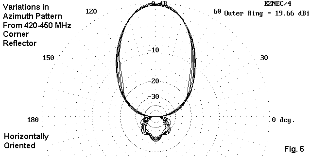
We turn to the horizontally oriented corner reflector in Fig. 6 with a similar set of patterns. However, the lack of significant variation in any of the noted parameters (gain, front-to-back ratio, and side lobe structure) makes it hard to believe that there are seven azimuth patterns overlaid in the graphic. Especially evident is the act that the front-to- back ratio never reaches a worst-case value as bad as 25 dB.

When vertically oriented, the corner reflector cannot quite match the rearward performance of the horizontally oriented version. As shown in Fig. 7, however, the side lobes exceed -20 dB at only one test frequency. moreover, the overall beamwidth is remarkably constant for a vertically oriented array. Compare this figure to Fig. 5, the corresponding pattern for the 10-element Yagi.

Fig. 8 makes the Yagi-corner comparison in the horizontal mode from a slightly different angle. Here we have elevation patterns for the Yagi and corner reflector overlaid, with color as our only hope of sorting out the lobe structure. In general, the Yagi wastes more energy at higher elevation angles than the corner reflector (at the 432 MHz design frequency). While the differences may not be yet decisive for any particular application, one begins to view the corner reflector as a well- behaved antenna.

The gain chart in Fig. 9 illustrates a number of things. First, even at a height above 13 wl, antennas designed for horizontal polarization show less gain when oriented vertically--over 0.5 dB. Otherwise, the gain curves are congruent for each type of antenna.
Second, the Yagi shows a rather distinct peak in gain, with significantly lower values (about 0.9 dB) toward the band edges. In contrast, the gain figures for the corner reflector vary by less than 0.4 dB across the band. We should also point out that systematic frequency sweeps earn their tedium time when they turn up unsuspected turns in the curves, for example, the corner reflector gain dip above 435 MHz. I have not investigated this dip to see if it is general for any type of reflector plane or whether it is unique to the choice of lengths and diameters used in this model.

The 180-degree front-to-back curves in Fig. 10 reveal a common Yagi trait: the peaking of the front-to-back value at a single frequency, with lower values elsewhere in the band. Although the DL6WU design has excellent gain across the band, the front-to-back ratio exceeds 20 dB for only a small portion of the spectrum.
In contrast, the corner reflector design varies by only 3 dB in front-to- back ratio across the entire 70 cm band. Unlike the Yagi curves for vertical and horizontal orientation, where the curves exactly overlay each other, the corner reflector shows some slight variations between orientations--but never enough to be noticed in operation.

In Fig. 11, we look at a property seldom mentioned in amateur antenna circles: -3 dB beam width. Here, we notice that the Yagi beamwidth decreases regularly across the band. In contrast, the curves for the corner reflector are much flatter, with slight peaks at those frequencies where we found the gain to fall off slightly. In general, we can add the beamwidth regularity to the evidence for the claim that corner reflectors are very well-behaved across a wide operating band width.
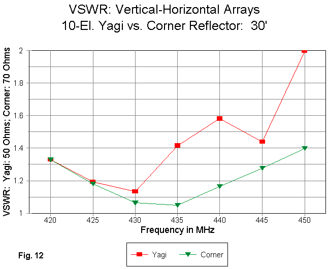
Accessing the operating advantages of each antenna type across a wide band, like the 420-450 MHz spread, necessarily involves taking the 2:1 VSWR curves of each antenna into account. Since the curves for each orientation within each antenna type are identical, only a single curve for each antenna type appears in Fig. 12.
If we think solely in HF terms, then the Yagi curve appears acceptable. For a field operation with short cable runs, the Yagi may be usable. However, for lowest losses in a fixed station environment with longer cable runs--even with high quality hardline--the SWR values over 1.5:1 (for a 50- Ohm standard, the design impedance of the antenna) can give one pause. In contrast, the corner reflector never exceeds 1.4:1 relative to the 70-Ohm driver design and placement for this particular model.
In contrast, there is little one can effectively do to increase the gain of a corner reflector. Different angles from the 90-degree reflector used here promise spot gain increase, but not very much and usually with a degradation of one or more other parameters. Placing parasitic arrays in the driver position is also of limited benefit, since the corner array is a "4-plane" design. Radiation rearward, upward, and downward all reflect forward, and predicting portions of the radiation pattern normal to a dipole does not yield enough gain to justify the reduction on operating bandwidth. In short, the corner reflector (within the limits of easily replicated designs) is yielding almost all that it can.
However, the corner reflector yields the same performance across the entire band. The 70 cm band is actually no challenge for a corner reflector, which has seen effective service over 2:1 frequency ranges. Let us make one last note of the categories in which we have seen consistent performance:
Within its gain limits, the corner reflector is a paradigm of a well- behaved antenna with consistent performance across an entire amateur band. For that reason alone, it is worth exploring a little further into the design featured in this part of these notes. Whether or not one wishes to built such a large antenna relative to its gain, what goes into the design should be intrinsically interesting.
However, one forewarning before we move onward. This part of the notes contains every last one of the pictures and graphics. Part 2 will feature tables instead. They are not as attractive, but they may be even more informative. Abandon aesthetics, all ye who enter Part 2.
DL6WU Original, 10 el 432 MHz           Frequency = 432  MHz.

Wire Loss: Aluminum -- Resistivity = 4E-08 ohm-m, Rel. Perm. = 1

              --------------- WIRES ---------------

Wire Conn. --- End 1 (x,y,z : in)  Conn. --- End 2 (x,y,z : in)   Dia(in) Segs

1            0.000,  6.705,  0.000         0.000, -6.705,  0.000 1.57E-01  19
2            5.465,  6.496,  0.000         5.465, -6.496,  0.000 1.57E-01  19
3            7.512,  5.937,  0.000         7.512, -5.937,  0.000 1.57E-01  19
4           12.433,  5.890,  0.000        12.433, -5.890,  0.000 1.57E-01  19
5           18.307,  5.819,  0.000        18.307, -5.819,  0.000 1.57E-01  19
6           25.134,  5.752,  0.000        25.134, -5.752,  0.000 1.57E-01  19
7           32.787,  5.693,  0.000        32.787, -5.693,  0.000 1.57E-01  19
8           40.980,  5.638,  0.000        40.980, -5.638,  0.000 1.57E-01  19
9           49.587,  5.594,  0.000        49.587, -5.594,  0.000 1.57E-01  19
10          58.606,  5.555,  0.000        58.606, -5.555,  0.000 1.57E-01  19

              -------------- SOURCES --------------

Source    Wire      Wire #/Pct From End 1    Ampl.(V, A)  Phase(Deg.)  Type
          Seg.     Actual      (Specified)

1          10     2 / 50.00   (  2 / 50.00)      1.000       0.000       I
Updated 4-18-99. © L. B. Cebik, W4RNL. Data may be used for personal purposes, but may not be reproduced for publication in print or any other medium without permission of the author.