 Some
Notes on NVIS Cloud Burners
Some
Notes on NVIS Cloud Burners
Mike had heard of trying to enhance the performance of a dipole at 70' up by adding another dipole, unfed and hence parasitical, about 1/8 wl below the first. He wondered if it might be even better to use a horizontal 1 wl loop at 70' and place a second loop below it, thus forming a sort of quad beam pointed straight up.
This led me to look at some models of both the dipole system and the loop system to see if the additional trouble, expense, and maintenance of a second wire would justify its entry into the antenna system. All models are via NEC using the Sommerfeld-Norton ground (since some wires will be less than 0.2 wl up). (See Modeling Note at the end of this item for more about modeling NVIS antennas.)
The basic criterion is this: we are trying for the highest elevation angle possible. Secondarily, the parasitical elements tend to lower the feedpoint impedance of the antenna system, and that might prove useful, if we want to feed the antennas with 50-ohm coax.
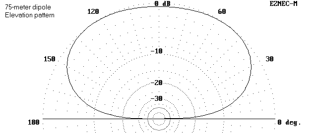
As the elevation pattern shows, the antenna gain reaches a maximum of about 6.1 dBi at about an elevation angle of 54 degrees over medium earth. The azimuth pattern at a standardized 45-degree angle is an oval, with the sides (off the antenna ends) about 5 dB down from the broadside peaks.
Adding a second wire is not quite so simple a matter as just placing a second wire 1/8 wl lower. First, the fed wire must be readjusted in length for resonance. Second the length and height of the second wire must be readjusted for maximum gain and for as close to a 50-ohm feedpoint impedance as possible.
The final model of this antenna used a driven element 121' long and a parasitical lower element 126' long. The lower wire was placed at the 30' level, 40' below the driven element for maximum gain and a good 50- ohm match. The feedpoint impedance of the array came in at just over 47 ohms.
As the elevation pattern below shows, the gain of the array is just over 6.2 dBi at an elevation angle of maximum radiation of 51 degrees. In practical terms, these figures are insignificantly different from those of the single dipole at 70' up. The azimuth pattern at 45 degrees elevation angle is an oval with the sides down about 4 dB from broadside maxima.

Whether it makes sense to install the second wire may depend upon what one considers the easiest way to achieve a 50-ohm match to the coax feed. To get any further gain out of this system requires a set of physical dimensions that yield a feedpoint impedance as far below 50 ohms as the original dipole impedance was above 75 ohms.
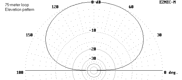
The patterns of the loop for cloud burners are more promising. As the elevation pattern below shows, the gain is about 6.3 dBi, with an elevation angle of maximum radiation of 77 degrees. The oval azimuth pattern shows only a 3 dB reduction in gain off the sides, relative to the line drawn through the feedpoint and the center of the opposite side. All of these figures are superior to either of the dipole cloud burners.
The feedpoint impedance remains a problem, although a 4:1 balun would certainly bring it close to a match for 50-ohm coax. However, perhaps a second loop might also help. Such a loop would have to be sized and spaced from the fixed driven loop to provide the best compromise between gain and feedpoint impedance.
The resulting model used a driven element at 70' up that is 63.4' on a side. The reflector is 66' per side at a height of 40' up, some 30' below the driven element. The resulting feedpoint impedance at resonance is just about 100 ohms. A 1/4 wl section of 75 ohm coax will transform this to a close match for 50-ohm coax.
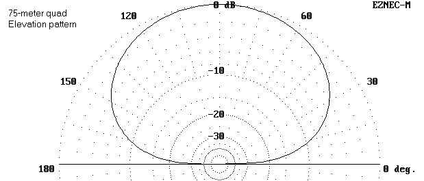
The elevation pattern shows that the maximum gain approaches 7 dBi straight up--well, 89 degrees, to be spuriously precise. The standard 45-degree-elevation azimuth pattern shows a depression in side gain of only about 2 dB. The near circularity of the pattern, plus the added gain and elevation angle of maximum radiation are presumed here to be desirable features.
The following pattern shows all 4 standardized azimuth patterns for comparisons. How significant the differences are, especially with respect to circularity, will be a user judgment.
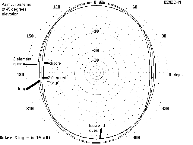
Of course, the quad loop array requires 4 supports, each at least 70' tall, whereas the dipole arrays require only 2 supports. Again, whether the increased upward performance justifies the added expense and effort will be a user judgment. The sketch simply illustrates the system differences.

First, the actual performance obtained will depend on all those variables of structure, materials, local ground clutter, etc. that enter into any antenna construction project. The pattern numbers are useful mostly for comparison, since they presume a common ground quality and a level, uncluttered antenna field.
Second, while cloud burning is a well-established practice among those who choose local and near skip contacts as their primary aim, there are numerous facets of the practice that are less well established. The precise radiation (and reception) angles needed for peak operation are here only presumed to be as straight up as possible. Reality may on occasion differ.
Nonetheless, if 4 properly spaced supports are available, the 2-element quad, hung up horizontally, may be hard to beat as the cloud burner of choice. If the supports are lacking, a single dipole at 70' up may be as good as it gets, being less than 1 dB down from the quad.
With about 64.25' of wire per side, the loop shows about 105 ohms feedpoint impedance, if fed in the middle of one side. A 1/4 wl 75-ohm matching section should provide a decent 50-ohm coax transition. (Remember that it is not necessary to feed the system with coax. Feed with parallel transmission line, the single loop at either 35' or 70' can be used as a general-purpose all band antenna, as notes on the all-band use of horizontal-plane loops suggest. Changing the feedline from coax to parallel line will not affect the loops pattern at 3.9 MHz. However, it is wise to use a link-coupled ATU to isolate the station from some of the inevitable noise pick-up. If all-band use is planned, length per side becomes less critical, and lengths from 65 to 70 feet per side are usable. Even distorting the shape into a squarish rectangle, trapezoid, or rhombus will not affect performance by much.)
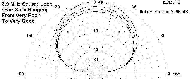
The pattern is straight upward, with a gain that ranges from about 5.3 dBi over poor earth to 7.9 dBi over very good earth, with a 6.7 dBi gain over medium earth. Beamwidth to half-power points is about 85 degrees. The pattern is oval, but the sides are down about 2 dB only. The following elevation patterns shows the gain range.
Fed at a corner rather than mid-side, the loop shows the essentially the same characteristics: above 6.6 dBi gain straight up, a beamwidth to half-power points of 85 degrees, and a 110-ohm feedpoint impedance. Ground clutter and construction variables will cause greater changes in characteristics than changing the position of the feedpoint.
This simplified system is almost as good as the parasitic loop system and far easier to build. The performance difference is unlikely to be noticeable in operation, while the savings in money and labor will be highly noticeable.
In the final analysis, after weighing all factors, the simplified single loop at 35' is perhaps one of the best cloudburners one might use.
I varied the height in increments of 0.05 wl from 0.1 wl through 0.3 wl, which allowed a peak detection over all of the soils used. The soil types used were the following, as found in the ARRL Antenna Book, following a classification in Terman:
Generic Name		Conductivity (S/m)		Dielectric Constant
Very Good		0.0303				20
Average			0.005				13  (Called "good" in EZNEC)
Poor			0.002				13
Very Poor		0.001				 5
A caution goes with this table. Wet soil does not itself guarantee an above-average soil condition. Measurements and analyses of the conductivity and the dielectric constant of ones soil within the ground reflection range of the antenna are necessary to determine with exactitude one's soil type. Hams come in two sorts: those who optimistically overestimate the quality of their soil and those who pessimistically underestimate it. Moreover, in the 75/80-meter band, soil penetration by the antenna's radiation is considerable, and most soils show considerable stratification. Hence, one's local soil type may in fact be a combination of different soil types. The NEC modeling system treats soils as homogenous.
The loop used was #12 copper wire 0.26 wl long on each side, with a corner feed. The feedpoint impedance varied with height, but also with differences of soil type. The following table is interesting:
Height	Height		   Soil Type vs. Feedpoint Impedance (R +/- jX Ohms)
WL	Feet		Very Good	Average		Poor		Very Poor
0.05	13.12		 51 + j93	 94 + j98	110 + j85	137 + j76
0.10	26.23		 71 + j74	 97 + j64	104 + j50	124 + j39
0.15	39.36		108 + j69	122 + j53	122 + j41	133 + j27
0.20	52.46		145 + j54	149 + j38	143 + j29	147 + j15
0.25	65.58		171 + j28	166 + j15	159 + j11	156 - j 1
0.30	78.69		180 - j 4	171 - j11	164 - j11	157 - j18
There is a rough correspondence of feedpoint impedance values at a height of 0.20 wl, with divergence both higher and lower. As the height changes, the values over very poor soil vary the least, while the values over very good soil vary the most.
The maximum gain curves for the loop at various heights of the different soil tops are more amenable to graphing.
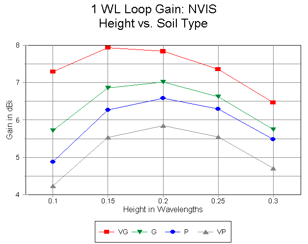
For all soil types worse than very good, the gain peaks in the vicinity of 0.2 wl. The peak gain occurs at a slightly lower antenna height over very good (and better) soils. Because the curves are fairly broad, there is likely to be little noticable difference in performance at heights between 0.15 and 0.25 wl. The 35' (about 1/8 wl) height used in the simple loop examples above appears to be a reasonably good height, but others within the range of typical home sites are equally usable. Once more, ground clutter and stratified soil will modify these results, which presume homogenous soil and flat, clear ground. Moreover, treating the ground directly beneath the antenna is unlikely to effect any significant improvement in gain, since the ground involved in the reflection of radiation extends well beyond the limits of the average amateur installation.
The single wire models (#12 and 1") used a split corner feed. The double wires were brought near to the feed corner (.707'), vertically connected, and a single wire run to the two lower corners. This 1' new wire was the feed segment. All loops had a top height of 52.46' (0.2 wl at the test frequency). Of course, the double #12 assembly has its lower wire 1' down.
Here are some results of interest.
Model		Side 	Seg./	Gain 	Feedpoint Z	Efficiency	Beamwidth
		Length	Side	dBi	(R +/- jX Ohms)			(Off Sides)
Single #12	67.5'	68	6.97	144.5 + j 1.3	97.72%		82.3 deg
Single 1"	68.4'	68	7.01	147.2 + j 0.3	99.82%		82.0 deg
Double #12	68.3'	68	7.04	144.2 + j 0.0	98.82%		81.8 deg
The maximum gain difference among the models is 0.07 dB. The maximum gain increase does not coincide with the maximum efficiency increase. Maximum gain does tend to coincide with a reduction in the -3 dB beamwidth. As an incidental, the -3dB beamwidths were recorded off the flats sides. Maximum and minimum beamwidths occur off the corners, with the maximum being in line with the feed point and the opposing corner. The range of -3 dB beamwidths is about 71 degrees to 96 degrees.
The upshot of this little exercise is that we gain little by going to more complex or difficult loop structures. In fact, the gain is so small as to be of numerical interest only to modelers. In practice, it would be wholly invisible. Indeed, one wet tree limb in the antenna field will likely have a much greater effect on gain than either double wires or fat wires.
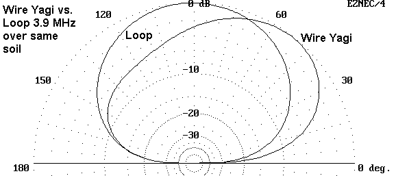
The figure shows the relative patterns of the loop noted above and the wire Yagi. Gain is virtually identical. However, the -3dB point "seaward" is almost directly overhead for the Yagi, while maximum gain is at an elevation angle of 53 degrees. There remains good gain in the region from overhead out to where the two patterns intersect, the region of primary interest for cloudburners, with the bonus of gain further on shore. A 75-meter low Yagi (1/8 wavelength up) can be thought of as more a signal director than as the "gain machine" we think of when we use similar antennas at 140' up on 20 meters.
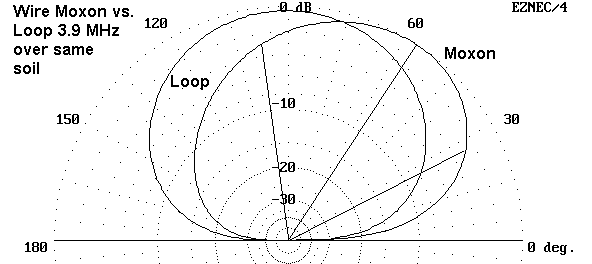
If you do not have the necessary 130' of yard width for a full size Yagi, consider a Moxon rectangle, which would require an area about 91' wide by 35' front-to-back. The Moxon does about the same job (with an insignificant 0.3 dB added gain) as the Yagi, as shown in the following pattern comparison with our loop. Maximum gain elevation angle is about 57 degrees.
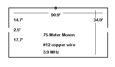
The Moxon does require a bit more care in construction. The gap between elements ends should be held as constant as possible. The model Moxon at 35' up for 3.9 MHz consists of #12 wire using the dimensions shown in the drawing below. The feedpoint impedance is between 50 and 60 Ohms.
For tilting the cloud burner pattern, either of these antenna designs is likely simpler and as effective as any complex phasing sheme between dipoles or loops. At least, they are likely to do the job until you tailor a complex antenna to fit your needs, your yard, and your budget.
If you need the pattern more overhead but not fully overhead--say somewhere between the loop and the Yagi/Moxon, you can always build one of the parasitic arrays at a 45-degree angle. If you cannot manage the full added height above the initial 35' level, you can bring the reflector closer to ground. Be prepared for changes in required dimensions and feedpoint impedance. The variations are too numerous and too site-specific to handle in these brief notes. I hope the principles involved are clear enough to whet your creative appetite. The designs may not truly burn the clouds, but "well-done" may be tastier in the long run.
Without exception, any antenna with a wire that yields radiation that is horizontally polarized, whether by direct or parasitic excitation, and that is less than 0.2 wl above ground, passes out of the limits of accuracy available in MININEC using its "real" ground system. This caution is well-published in the instruction manuals for the extant commercial versions of MININEC (for example, AO, EZNEC, and NEC4WIN). Indeed, a safer limit for accuracy over ground may be above 0.25 wl.
In contrast, the Sommerfeld-Norton ground system associated with NEC (at least from versions -2 through -4) is capable of providing more accurate results. Typical programs using NEC are EZNEC, NEC-Wires and NECWin (Basic, Pro, and GNEC).
We can illustrate the potential for MININEC to give erroneous reports for horizontal antennas close to ground by setting up a model 132' #12 copper wire dipole for 3.9 MHz placed 30' above ground--just a tad below 1/8 (0.125) wl. One version of MININEC reports the gain (straight up) as 8.10 dBi, with a source impedance of 30.4 + j11.7 Ohms. In contrast, the same antenna at the same position is reported by NEC-2 to have a gain (also straight up) of 5.68 dBi, with a source impedance of 53.5 + j11.5 Ohms. The gain difference is 2.42 dB, a very significant difference indeed. The lower gain reported by NEC does not mean that the antenna would not perform its intended function. It would mean that the gain required to perform that function is less than MININEC suggests that we need.
If we place both antennas over perfect ground, MININEC reports a gain (straight up) of 8.49 dBi with the same source impedance recorded above. NEC-2 reports a gain (also straight up) of 8.50 dBi with a source impedance of 30.7 + j16.0 Ohms. Over perfect ground, the two programs are reasonably consistent. The fact that the gain of the antenna over real ground, even in MININEC, is less than over perfect ground can mislead us into thinking that the MININEC real-ground report is accurate. It is not.
Typically, for antennas that pass below the real-ground 0.2 wl height restriction for MININEC, the gain is over-reported. In the example we set up, the over-report is misleadingly large. To this problem, we may also add the fact that MININEC reports the source impedance with respect to perfect ground, regardless of the actual ground and quality selected by the user. Real ground selections in MININEC affect only far field patterns, but not the source impedance. The "perfect ground" source impedance only begins to approximate the actual source impedance of an antenna over ground when the antenna is quite high. Horizontal antennas especially display wide variations of source impedance as they are placed at various heights below 1 wl. About the only thing that does hold up with any accuracy in a MININEC model of a horizntal antenna at a very low height is the basic shape of the low dipole pattern, but without the gain values attached.
Consequently, a MININEC model of a cloud-burner can only tell us that the pattern appears to be correct for NVIS use. The gain report is likely to be higher than in reality. Any coincidence between the reported source impedance and that encoutered when building such an antenna will be purely coincidental. Because of MININEC's limitations in this regard, it would be prudent to cross-check any MININEC model of an NVIS antenna against NEC models of the same antenna.
In contrast to MININEC, NEC-2 is quite adequate for reporting predicted gains and source impedances (as well as pattern shapes) for most types of wire NVIS antennas and arrays. When wires are brought to within 0.001 wl of ground, inaccuracies may set in, but at 3.9 MHz, that figure represents a height of a little over 3" or so. If modeling NVIS cloud-burners is your interest, please be sure that the software you use is adequate to the task.
Updated 3-15-98, 1-12-99, 3-15-99. © L. B. Cebik, W4RNL. Data may be used for personal purposes, but may not be reproduced for publication in print or any other medium without permission of the author.