 The Birdcage Antenna
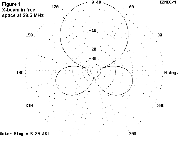
We may legitimately ask, how much better does the whole Birdcage work compared to an X-beam? When Dick Bird, G4ZU, published his work in 1960, he made some fairly extravagant claims for the antenna, claims that led him to patent it.(2) At this distance and with the calculating power made available by NEC and its offspring, we may decide that the claims for his antenna (and those of many hams who built one) reflect more accurately the low state of home-brew Yagi and quad construction of the time than they do contemporary comparative performance. Models of the Birdcage show little advantage over the X-beam and exaggerate some of its limitations.
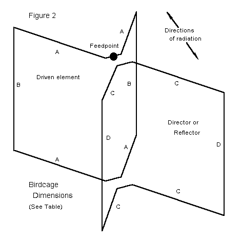
Bird graphically demonstrated what he took to be the principles of the Birdcage by beginning with the bidirectional pattern of the dipole. Folded into a Vee, the antenna would show, according to his sketches, a strong lobe out the open end and a weak lobe off the apex. Add a Vee reflector (pointed the other way to make an X), double the assembly a quarter wave above or below, bend the X-arms vertically to meet each other as phasing lines, and the Birdcage is born. Figure 2 shows the outline of the Birdcage, with identification of each relevant dimension.
Unfortunately, the seeming flaw in the reasoning begins with the Vee itself. Short Vees do not cancel the radiation off the backsides of the elements (the outsides of the V). Thus are born the uneliminable quartering lobes of the X-beam and even larger lobes for the Birdcage.
Birdcages come in two forms: with a reflector and with a director. Table 1 shows 10-meter models of each beginning with a self-resonant Birdcage with equal-size elements derived from data given in 1960's literature.(3)
Table 1.  Modeled Dimensions of the Birdcage Antenna

Dimensions     DE Arm (A)     Parasitic (C)       Vertical (B and D)
               L (ft)         L (ft)              L (ft)
Basic
 Birdcage      5.05           5.05                8.666

DE and Refl
 Resonated     4.95           5.26                8.666

DE and Dir
 Resonated     5.16           4.91                8.666

Note:  all models used #14 copper wire in free space at 28.5 MHz on NEC-4.
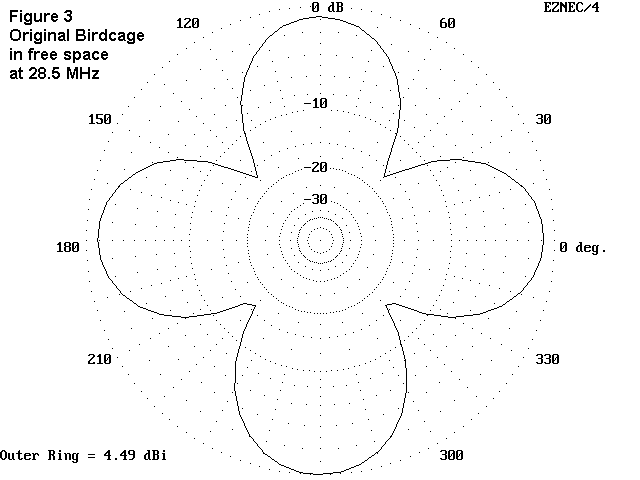
Figure 3 shows the performance in free space of the basic Birdcage--a nice 4-leaf clover.
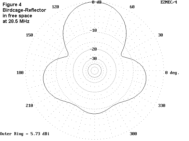
G4ZU favored the reflector version, which is perhaps the worse performer of the two possible versions. With a forward gain in free space of under 6 dBi and a front-to-back ratio of about 8 dB, the beam is not the equal of a 2-element Yagi or even of the X-beam. Figure 4 shows its performance in free space.
The director version that parallels the development of the X-beam provides more gain and front-to-back ratio: 6.3 dBi and 17 dB, respectively. Figure 5 shows its performance in free space. The direction is reversed, since I simply re-dimensioned the reflector to form a director.
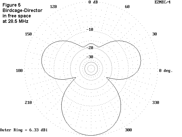
As shown in Table 2, the figures for the directed Birdcage surpass both the X-beam and the 2-element Yagi by a small bit, while the reflected Birdcage leaves much to be desired.
Table 2.  A Comparison of Antenna Performance
Antenna             TO Angle  Gain      Front-to-      Feedpoint
 Type               (degrees) (dBi)     Back (dB)      R ñ jX (Ohms)
A.  Free Space
Birdcage: DE + Ref  --         5.8       8.0           34 -  0
Birdcage: DR + Dir  --         6.3      16.9           40 +  4
Folded X-Beam       --         5.3      39.1           37 -  3
B.  Height = 5/8 wl
Birdcage: DE + Ref  22        10.5       8.0           31 -  3
Birdcage: DR + Dir  22        11.0      17.1           40 +  3
Folded X-Beam       23        10.5      21.8           35 +  0
2-El Yagi           23        11.3      10.9           34 -  5
2-El Quad           22        11.7      18.3           97 -  3
C.  Height = 1 wl
Birdcage: DE + Ref  13        11.3       8.6           32 -  2
Birdcage: DR + Dir  14        11.8      17.0           39 +  2
Folded X-Beam       14        10.8      31.7           33 -  1
2-El Yagi           14        11.7      13.5           35 +  0
2-El Quad           13        12.4      17.9           92 +  8
Note:  TO angle=the angle of maximum radiation at which azimuth readings of
calculated gain and front-to-back ratio were obtained.  All calculations
via NEC-4.
The pattern of the Birdcage in either version does not meet today's standards of front-to-side ratio or front-to-rear ratio. The quartering rear lobes of the X-beam become virtual side lobes of the Birdcage and are only down from the main lobe by some 4 to 5 dB in the either version. There is little QRM-rejection potential, especially in the reflector version. Over real ground, the pattern devolves into a mound of whip cream. However, over real ground, the director version tends to push its side lobes to the rear, and the pattern begins to resemble that of the folded X-beam.
Like the folded X-beam, the Birdcage retains its most optimal pattern only over a small portion of the band of design. The reflector version rapidly grows a tail below design frequency, while the director version grows its tail above design frequency. The SWR bandwidth is also narrow, less than 0.5 MHz at 10 meters for a 2:1 SWR. However, the complex structure of the Birdcage is less amenable to a tunable parasitic element than is the simpler X-beam.
All in all, the additional complexities of the Birdcage are not warranted by a significant increase in performance over the X-beam. Gain aside, the side and rear performance of the antenna falls far short of other compact designs. Consequently, while that antenna has a great name and an appealing look, performance models do not recommend the investment of time and resources in this antenna. In some ways, it is a shame to discover this: G4ZU contributed extensively to amateur practice in the field of antennas. Although the Birdcage antenna has had its day, Dick's other work--and his example--will long endure.
(2) Dick Bird, G4ZU, "The G4ZU 'Bird Cage' Aerial," CQ (April, 1960), pp. 40-42, 117.
(3) See George Cousins, VE1TG, "The Tri-Band Birdcage," CQ (July, 1963), pp.
30-33. Another brief reference to the antenna occurs in Orr and Cowan,
Cubical Quad Antennas, 3rd Ed. (Lakewood, NJ: Radio Amateur Callbook,
1993), p. 102, where it is shown with a reflector and referred to as a
variation of the quad.
Updated 3-18-97 © L. B. Cebik, W4RNL Data may be used for personal purposes, but may not be reproduced for publication in print or any other medium without permission of the author.