


Among the more usable of the large wire antennas is the loop that is at least 1 wl long at the lowest frequency of operation. However, large loops belong to three different families, each with distinct characteristics.

Fig. 1 shows the three families of antennas. VOVPLs are vertically oriented, vertically polarized wire loops, such as the delta and the rectangle when we feed them along the side. They stand upright and vertically polarized radiation is broadside to the antenna plane. Ordinarily, VOVPLs are monoband antennas and perform less well than their relatives when pressed into service on other bands.
VOHPLs are vertically oriented, horizontally polarized wire loops. The quad loop fed along a horizontal wire is the most popular member of this group, although horizontally polarized triangular antennas are also common. VOHPLs show significant superiority over VOVPLs in all band use. However, they have two limitations. First, if we can place a wire doublet at the top height of the VOHPL, it will usually show a lower angle of maximum radiation, because the VOHPL's radiation is a combination of the upper and lower wires. Second, to be a truly large loop of 1 wl or greater, the VOHPL requires exceptionally tall supports.
For the ham with more area than height in his yard or field, a more frequent selection is the HOHPL: the horizontally oriented, horizontally polarized large wire loop antenna. The standard installation is to place the loop as high as one can, with only the placement of supports and the overall yard size as restrictions on the loop length. Loops up to several wavelengths long around their perimeter are in use on 80 meters--and on all of the bands above.
(We should note in passing that there is no known HOVPL, that is, a horizontally oriented, vertically polarized large loop antenna.)
HOHPLs can be strung around the edge of a yard, meaning that even a city lot whose perimeter is at least 280' long can support a 1 wl version at 80 meters. Such a lot is about 70' by 70' if square. If the yard width is only 50', then the yard need only extend 90' back to hold the antenna. With allowance for sidewalks, flower beds, trees, and the like, there is still room for a HOHPL in many more ham homesteads than we might think. Therefore, the entire class of HOHPLs deserves a longer look to discover their strengths and their weaknesses.
Let's develop a plan of attack for understanding HOHPLs. The first part of our work will include some answers to the most pressing questions about HOHPLs:
The second part of our effort will be devoted to a compendium of modeled antenna patterns to give you some idea of what to expect from HOHPLs. Some of the answers we give to questions just outlined will become graphically clear when we peak at a number of antenna patterns.

The circular HOHPL outlines in Fig. 2 show my best suggestion: make the loop larger than 1 wl. A 1 wl horizontal loop that is less than 1/2 wl above ground tends to be a cloud burner. NVIS (near vertical incidence skywave) antennas are certainly useful--and desirable to certain types of operation. But they have very poor DX potential.
By the time a loop is at least 2 wl long at its fundamental frequency of operation, it looses its ability to warm the clouds and becomes an antenna with some potential for longer distance communications. so the general rule for HOHPLs is this: make them as long as you can support in your yard.
These notes apply to the use of a HOHPL at the lowest desired operating frequency. However, longer is not always better if our main interests are at the upper end of the HF spectrum. As we shall see, a desire to operate on both 80 and 10 meters with a HOHPL may provide us with a bit of a dilemma.
Although I shall be speaking in terms of 1 wl and 2 wl HOHPLs, there are no rules against making them even larger or against making them some non- integral multiple of a wavelength. In some respects, we can say with assurance that performance of a 1.5 wl HOHPL will be intermediate between a 1 wl and a 2 wl version. However, as we shall discover, there are enough variations in the performance of a 1 wl HOHPL to make my claim fall among the world's most vague statements.
Before we speak in geometric terms, let's note a mechanical issue that will be involved in the shape decision. Besides the position of the supports for corners, we must also take into account the length of each side vs. the strength of the wire used to form the HOHPL. Assuming the availability of supports, we would normally place supports at distances to protect the antenna from undue stress, especially stress due to weather. Wind and ice are the major enemies of large loop antennas with long wire runs.
Copperweld is a good material for a long wire loop and may call for fewer supports than soft-drawn copper wire. Although heavier than pure copper, quality copperweld wire has many times the strength. However, another reality of HOHPL construction is that hams tend to use whatever bargain wire they can find at hamfests, close-outs, and other inexpensive sources. If you choose the economic route, be prepared to splice breaks during the life of the antenna.
Realities of ham antenna farms usually breed irregular shapes for HOHPLs. These shapes are not only usable, but as well they can be modeled and analyzed. However, we can only do this on a case-by-case basis. For our work today. we must confine ourselves to regular polygons. You may think of any regular polygon as a greater or lesser approximation of a circle: the more sides to the polygon, the closer the approximation to a perfect circle.
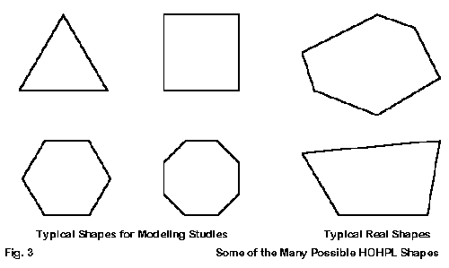
Fig. 3 Illustrates some of the typical geometries used in constructing making HOHPLs of both regular and irregular shape. We shall from here on confine ourselves to the regular shapes. Our reason is a matter of both the general application of the ideas and the ease of making calculations.
Regular polygons have some dimensions that are especially useful in planning and calculating the various antenna dimensions. Fig. 4 shows them in outline form for the triangle through the octagon. Note the Side (S), radial to a peak (A), and radial to a side (H).

Table 1 lists some of the relationships among S, A, H, and C (the overall circumference or total wire length of the loop. Note that the more numerous the sides, the closer the lengths of A and H to each other. A circle, with an infinite number of sides from a geometric perspective, finds A and H to be equal.
                                Table 1.  Figuring a Regular HOHPL

                                   A.  Deciding the Wire Length

L = wire length = 300 / Fl (meters) = 984 / Fl (feet)            Fl = lowest frequency used in MHz
L (1.8 MHz) = 167 m = 547'                                               L (3.5 MHz) = 86 m = 281'

                               B.  Figuring the Layout (See fig. 4)

C = length of circumference             S = length of side        A = length of radial from center
                             H = length of X or Y from center of loop

I.  Triangle                                        III.  Hexagon
S = C / 3                                           S = C / 6
H = 0.29 S          (= 0.10 C)                      H = 0.87 S          (= 0.14 C)
A = 0.58 S          (= 0.19 C)                      A = S               (= 0.17 C)
A + H = 0.87 S      (= 0.29 C)

II.  Square                                         IV. Octagon
S = C / 4           (= 0.25 C)                      S = C / 8
H = 0.5 S           (= 0.13 C)                      H = 1.2 S           (= 0.15 C)
A = 0.7 S           (= 0.18 C)                      A = 1.3 S           (= 0.16 C)

V.  Circle                                          VI.  "Irregular"
A = H = 0.16 C                                      String wire along ground and adjust
The table of relationships is especially handy when you begin the process of planning a HOHPL with a paper sketch of your yard space. They are also handy if you wish to calculate the wire end coordinates on an antenna modeling program. The main shapes that we shall focus on in generating patterns for possible HOHPLs will be the square, the hexagon, and the octagon--the last because it most closely approximates a circle.
You may locate the feedpoint of a HOHPL at any point along its length. Mechanically, this usually means intersecting the antenna at the position that allows the straightest line from the antenna to the shack entry point. For some installations, the feedpoint may be at a corner (or junction of sides); for others, the feedpoint may be centered on a side--or even off- center on a side.
One of the surprises that modeling the HOHPL produced is this: at what point you feed the antenna does make some difference in the resulting pattern on at least some of the bands in the HF region. As we shall see, when we explore the antenna over many ham bands with several geometric configurations, even the octagon fails to act like a circle on some of the upper HF bands. When we look at the patterns of the various antenna versions, keep in mind where you want the lobes and nulls to be relative to your own possible installation. A less direct feedline might yield a superior pattern relative to your operating desires.
At this point I shall make a brief pitch for every serious antenna buff to acquire at least one of the antenna modeling programs. There is no reason for us to simply accept what a roughly constructed antenna might give us. We can plan and tame the beast-- whether by relocating wires or relocating the feedpoint--to give us the best compromise of lobes going just where we want them.

The most ideal and yet practical arrangement for supporting a HOHPL corner appears in Fig. 5. Note that the system includes a pulley and rope for raising and lowering the wire. A cleat near the ground is useful for tying off the rope. I have also used rope loops and clip rings at the cleat level. I disconnect the extra rope used only when lowering the antenna and store it out of the weather. I clip the upper rope to a hook instead of a cleat. When I need to lower the antenna, I add the extra section, which is long enough to reach but not pass through the pulley.
A slip ring can be made from almost any plastic, although I tend to prefer Schedule 40 PVC Tee fittings for their durability. Their smooth interiors also tend to minimize wire kinking and rubbing, thus prolonging the life of the antenna. I do not offer these mechanical notes as a final and best answer to every situation. Instead, I hope that they get you to think about the mechanical details of your antenna as being just as important to its successful performance as the electrical details.
Electrically, the question of HOHPL height is a matter of the elevation angle of the radiation. We can best picture what height means to use if we select an antenna design, a set of heights, and a few test frequencies. So let us take a square HOHPL that is 1 wl long at 80 meters and place it 35' up, 50' up, and 75' up--all typical ham installations. Now let's see, with the aid of computer modeling, what happens. But first, be sure to understand that antenna modeling presumes flat terrain with no ground clutter. Hence, the results will be very general.

Fig. 6 demonstrates the difficulty of using a HOHPL at its lowest frequency (where it is 1 wl long). The 1 wl loop radiates predominantly broadside to the plane of the wire, which is straight up and down. Even at 75' up, the antenna is a "cloud-burner," or a suitable candidate for NVIS (Near Vertical Incidence Skywave) service.

On 40 meters, as the patterns in Fig. 7 show, the antenna begins to form patterns that are suited to normal skywave communications. However, the antenna is still a bit low when under 75' up, so the angles of maximum radiation are 37° at 50' up and 44° for 35' up. Longer distance effectiveness is enhanced by raising the antenna to 75' up, where the angle is about 26°.

On 20 meters, as illustrated in Fig. 8, the same antenna begins to show excellent DX potential. At 35' up, the elevation angle of maximum radiation is 26°, with angles of 19° and 14° appearing at heights of 50' and 75', respectively. The emergence of higher angle secondary lobes becomes apparent, but these lobes are generally not as large as those that form with doublets at the same height.

On 10 meters, as revealed by the patterns in Fig. 9, the HOHPL become an excellent DX antenna, with very low elevation angles of radiation: 12°, 9°, and 6° for heights of 35', 50', and 75' respectively. (Remember that the lobes have a vertical beamwidth so that the angles cited represent the center points of reasonably broad angular spreads that can handle propagation angles somewhat distant from the center line.)
If the HOHPL has a significant weakness, it lies in the operation of the antenna at its fundamental frequency. To some extent, this weakness can be ameliorated by further elevating the antenna. A better solution, if land area is available, is to build a longer antenna, so that the fundamental frequency is lower. When the antenna is operated at its 2nd harmonic (when it is 2 wl long), the primary radiation is mostly in the same plane as the wire loop. Elevation angles at 80 meters will still be high, but not nearly as high.

Compare Fig. 10 to Fig. 6. Although the elevation angle on 80 meters for the 2 wl loop is not ideal, it is considerably better than the elevation angle of the 1 wl version.
Therefore, let's look at a compendium of azimuth patterns for the HOHPL using a variety of configurations to sample the territory. (Remember that a full set of patterns would use up a book, so we must restrict ourselves to a relevant sample.) We shall look at 1 wl antennas in the square and the octagon configurations, each fed at the center of a side and at a corner. Then we shall repeat the process with a 2 wl long hexagon as a sample of a longer HOHPL. From these examples, you can likely extrapolate what might happen with a large loop placed in your own yard.
In all cases, the feedpoint of the antenna is placed at the left-most point on the antenna relative to the pattern shown. This procedures gives you a fair comparison, especially of patterns that are too complex to place in a single figure by laying one pattern on top of the other. In some cases, it would be impossible to keep track of which lobe belonged to which antenna. Therefore, we shall use separate figures and devote one page to each of the amateur bands for the 80-meter antennas--and a column to each band for the 160-meter model.

Any differences of performance among the loops shown here are too small to detect in operation, amounting to only 0.07 dB. The basic pattern of the loop at its fundamental frequency is a broad oval, stretched in the direction through an axis running from the feedpoint to a point on the opposite side of the loop. The loop "sides" are only a little over 2 dB down from the gain maxima.

All of the loops in this long sequence of azimuth patterns have been modeled so that the feedpoint is to the far right, whether that point is in the middle of a side or the point where the wire takes a new direction. The orientation of the loop is shown only for the 80-meter azimuth patterns. However, the loop and feedpoint positions do not change as the modeling runs increase in frequency on succeeding pages. You can draw your own North line on each pattern.

For all of the loops shown here, the 3.5 MHz azimuth patterns have been taken at an arbitrary 45° elevation angle. The actual elevation angle of maximum radiation on 80 meters is 90° or straight up for these loops, which are 1þ long. If you compare these patterns with Fig. 6, you will see that there is very little low elevation angle radiation on 80 meters, since the basic radiation pattern is broadside to a 1 wl loop.

On 80 meters, an 80-meter loop arranged as a HOHPL makes a very good NVIS (near vertical incidence skywave) or cloud burner antenna. Long- distance contacts will likely be rare on 80 meters, although contacts within a 300-500 mile radius may be stronger than with some other types of antennas, such as verticals and inverted Vees. See the 80-meter patterns of Fig. 15 and Fig. 16 for an alternative, composed of 2 wl loops at 80 meters.

Both the loop shape and the feed position begin to make themselves evident on the 40-meter azimuth patterns. Elevation angles of maximum radiation run from 37° to 43° for these 1 wl loops at 7 MHz, which allows direct comparisons among the azimuth patterns. Beginning with the square loops, we can examine them a pair at a time.
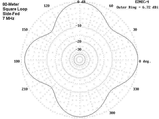
The square loops show a very distinct difference in shape and gain that depends upon the feed point. The side-fed model shows stronger lobes (by almost 0.8 dB) and deeper nulls. In contrast, the corner-fed model is a round-cornered diamond, with a bit less gain in the direction of the feedpoint. Moreover, the points of maximum gain for the corner-fed model are to the sides, that is at right angles to the axis passing through the antenna feedpoint and the point opposite it on the antenna loop.

In contrast to the differences between patterns depending on the feedpoint for the square loops, the octagon loops show an almost insignificant difference in pattern, whether the antenna is fed at a corner or in the middle of one side. The smaller differences also show up in the feedpoint impedances, with the squares showing a large difference as the feedpoint is moved.
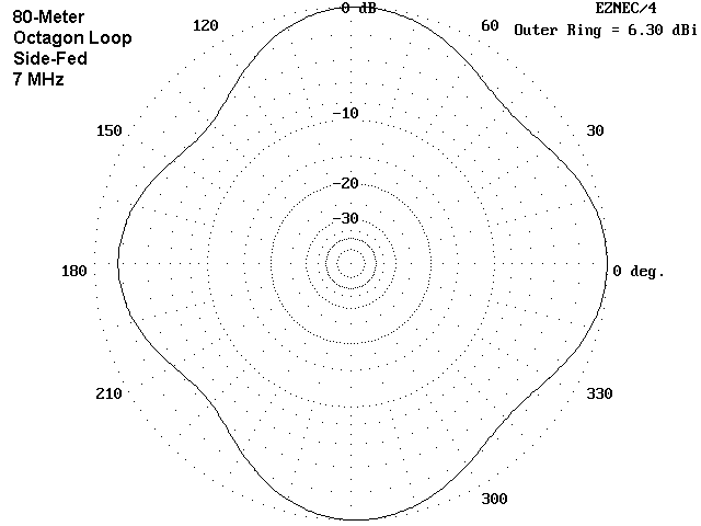
The simultaneous change in both pattern and feedpoint impedance in the square models indicates that the diamond and square configurations make a difference in the current distribution and interaction as the turned with the change in feedpoint. At 40 meters, the effect is much less for the octagon, since the difference in length between a radial to a corner and a radial to a side is much smaller. Whatever the differences, all four of these loops would make very good omni-directional antenna for 40 meters.

On 80 and 40 meters, the loops are close to resonance. Sometimes, differences show up most graphically when an antenna is operated at a frequency for which it is not resonant. For all of the loops, the feedpoint reactance is in the vicinity of 600 Ohms at 10.1 MHz. Once again, the squares show a stronger pattern difference that depends solely on the feedpoint selection.
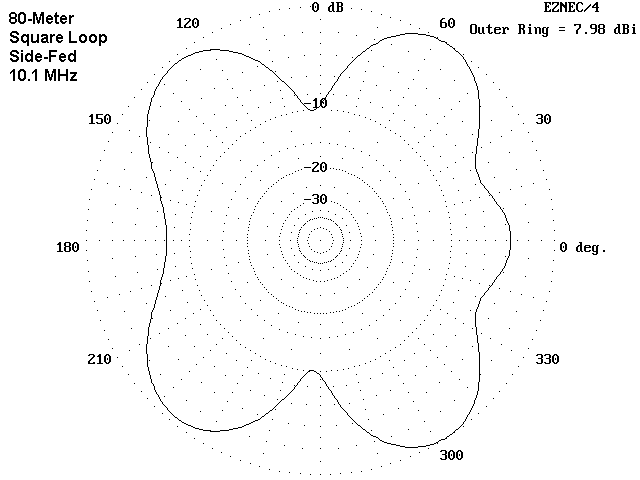
When fed at the corner, the 30-meter square pattern becomes very bi-directional, with about a 2 dB front-to-back ratio and about 8 dB or more front-to-side ratio. The distance from the feedpoint to the opposite peak is about 3/8 wl. In contrast, the side-fed square feedpoint is only about 1/4 wl from the opposite point across the square. Radiation remains strongest off the corner peaks, and the gain along the feedpoint axis is nearly 7 dB down from the forward gain of the corner-fed model.

Once more, the octagon-shaped models show much less difference that can be attributed to the selection of the feedpoint position. Although there is little operational difference between the two octagons, it is interesting to note minor pattern tendencies. For example, absolute gain maxima do not appear in corresponding positions.

In addition, the nulls of the side-fed octagon are slightly deeper than those of the corner-fed model. This feature shows a kinship between the side-fed square and octagon models.
In all, three of the four arrangements make very respectable omni- directional antennas. Only the corner-fed square arrangement is less suited to this service and better suited to bi-directional operation that requires careful antenna orientation for effective use.

On 20 meters, the elevation angle for the loop, whatever its shape or feedpoint position, has decreased to about 20°. This angle (a product of the 50' height for all of the models) places the antenna radiation into the DX range, although signals would be stronger with the antenna even higher. On 20 meters, the antenna planner is faced with further decisions.
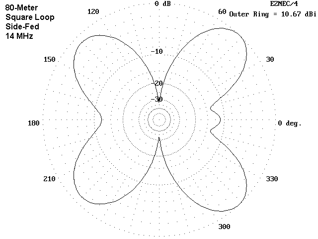
The square loop shows major lobes near or above 10 dBi off each of the four corners. The lobes of the side-fed model are broader, which would lessen the problem of orienting the antenna toward desired areas of the world. In contrast, the narrower but stronger lobes of the corner-fed square would provide a gain advantage, especially in three of the four directions that the antenna favors. The cost of the added gain is a collection of very wide and deep nulls in the pattern, which would effectively limit communications in many directions.

In contrast, the octagons seem once more to have very similar patterns to each other, regardless of the feedpoint position. However, note the fact that the lobes are a function of feedpoint position and not of whether there is a side or a corner at the lobe location. This factor shows up in the differential in the feedpoint impedances for the two octagon models.

What the octagons lack in maximum gain, they make up for in omni- directional potential. Although nulls can be as deep as 10 dB below the lobes, they cover less territory and are shallower than most of the nulls in the patterns for the square models. The lesson here is simple: if 20 meters is a desired band for operation of a HOHPL and if one wishes to work in every possible direction, then the HOHPL should be as round as one's terrain permits. The squarer the shape, the larger and deeper the pattern nulls.
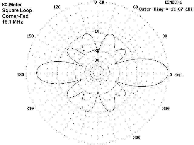
The patterns for 17 meters appear to have no rhyme or reason--indeed, they seem to suggest an error in modeling. However, they are as correct as NEC-4 can make them. Once more, nonresonant operation of the loop permits the current distribution to change radically with small changes of configuration. The result is a diverse set of patterns.

The corner-fed square shows a high-gain bi-directional pattern that is similar to and in line with the 30-meter pattern for the same model. Maximum gain is off the corners that are in line with the feedpoint. The side-fed square also shows its maximum gain off the corners. However, since the feedpoint is between corners, the gain is more evenly distributed among all four corners. Hence, the apparent major difference in the operation of the loops turns out to be smaller than at first sight, but very significant for planning.
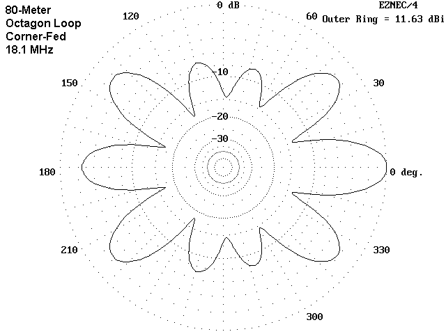
The corner-fed octagon pattern shows its affinity to the corner-fed square with a noticeable but less extreme bi-directional pattern. The greater "side" gain results in a lower gain along the major axis of the antenna, compared to the square. However, the "side" gain is not sufficient to qualify this arrangement as having good omni-directional potential.

The pattern for the side-fed octagon may seem initially mysterious. Twisting the antenna and moving the feedpoint by only 22.5° alters the axis of highest gain by 90°. Part of the mystery begins to clear up when we note that the antenna is attempting to produce 10 lobes from 8 sides and 8 corners. Since the antenna is over 5 wl long at 18.1 MHz, current distribution and resultant gain distribution can change rapidly with small changes in antenna configuration. Since 17 meters is less widely used, these difficulties are usually minor.

The tendency of a square loop to radiate with maximum gain from its corners continues on 15 meters. The elevation angle is in the 13-14° region, which gives the antenna significant DX potential. The strongest lobe of the corner-fed square has a gain rivaling a 3-element Yagi, but over a much narrower beamwidth. (We should especially note this fact, because wire antenna makers often advertise their wares as equal to beams. The illusion only persists if we ignore beamwidth.)
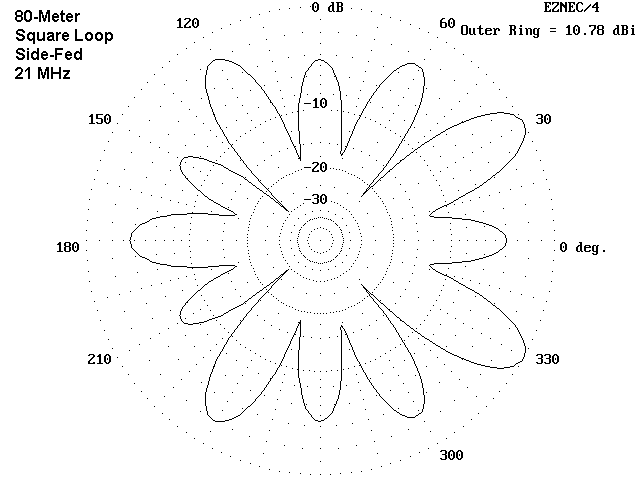
With corner feed, current magnitude and phase combine to yield 4 strong, narrow lobes with corner feed. With side feed, the major lobes become many (12, to be exact), well spread around the horizon, but at loss of over 3 dB of maximum gain. (Note that the corner-fed version also has 12 lobes, but 8 are very minor.) The side-fed square becomes the configuration of choice if we desire maximum coverage on 15.

Like the 17-meter model, the 15-meter models of the octagon show far greater similarity than do the square models. The corner-fed version retains a bit of the 4-lobe dominance found in its square counterpart, but the minor lobes have grown into major ones, giving the antenna better potential for omni-directional contacts. However, the side-fed octagon has the most even pattern of all, with only a small tilt of the pattern away from the feedpoint.

As has been the case on other bands, the feedpoint impedance differs most widely between the two square models, with considerable less difference between the two octagon models. The corner-fed square has a lobe with the highest gain of the four models. In contrast, the highest gain of the very even-lobed side-fed octagon is about 4 dB lower than the corner-fed square. Even lobes usually means lower maximum gain.

The 12-meter corner-fed square continues the pattern of bi-directionalness on this model on the non-harmonically related bands. As was the case with lower band models, the highest gain is along the axis from the corner feedpoint through the corner opposite. When side fed, the square once more shows maximum gain from the four corners of the loop.
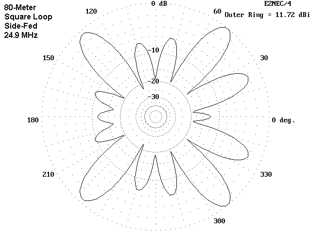
The loop which is 1 wl long on 80 meters has 14 lobes, or 7 per half loop on 12 meters. This is no accident, since the length of the loop at 24.9 MHz is a little over 7 wl. (On 80 meters, the loop showed only two lobes in the oval pattern, 1 per half wavelength.) As the side-fed pattern shows, some lobes may be very small. In other cases, lobes may merge to become almost indistinguishable from a single lobe. However, you can always count on them being present as a function of the length of the wire at one lobe per half wavelength.

The 14 lobes of the 12-meter octagons are clear and distinct in both the corner and side fed versions of the antenna. In the octagons, the lobes are functions of the feedpoint in terms of direction. However, the difference between the two feed positions shows up in the minor differences in the relative strengths of the individual lobes, except for the one directly opposite the feedpoint.
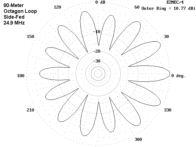
Interestingly, the 12-meter models are as a group closer to resonance than any other group. The bi-directional corner-fed square shows the highest reactance. The other models, with there more even collection of lobes, show between 20 and 75 Ohms reactance. You may track the feedpoint impedances in the reference table that immediately follows this compendium of azimuth patterns. You may find it useful to correlate the pattern descriptions, the maximum gains, and the feedpoint impedances of the models.

28 MHz is exactly 8 times 3.5 MHz. since the loops at 80 meters had two lobes, we should be able to count 16 lobes in the 10-meter models. In fact, the square models only show 12 lobes. What has happened to 4 lobes? In principle, two things can occur. One is that the lobes merge. In most instances, merges lobes show some aberration of the normal cigar shape of a lobe. No such odd shape appears in the square models.

The other possibility is that lobes cancel each other due to the presence of equal but opposite radiation from symmetrical points across a loop. In the corner-fed model, notice the wide and very deep nulls at the 45° angles, and in the side-fed model, notice similar nulls at the 90° points. Both sets of nulls correspond to the middle points along the sides of the squares. In effect, the lobes for these positions have cancelled each other out across the antenna loop.

The relative positions in the octagon that might correspond to those in the squares are not quite right for complete cancellation of any lobes. Hence, the full complement of 16 lobes appears in each of these models. The corner-fed octagon shows its strongest lobes on either side of the position where the corner-fed square has its strongest lobe. The side-fed octagon positions its strongest lobes like those of the corner-fed square.

The side-fed octagon also illustrates lobe merging and the consequent distortion of lobe shape as two or more lobes come together. The "mittens" at 135° and 225° are good examples of merging lobes.
It is clear from this compendium that loop shape can make a difference in how the loop performs on various bands. If you plan to build an irregular loop, by all means, anticipate its performance through modeling.

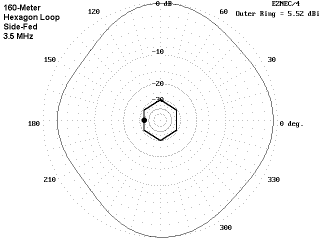

On 40 meters, the 160-meter loop becomes quite bi-directional with either corner or side feeding. Maximum gain occurs off opposite points of the hexagon. with corner feeding, the axis of maximum gain is through the feedpoint to the opposite corner. However, if we side-feed the hexagon, the axis of maximum gain is at right angles to the feedpoint-to-opposite side axis.
Both of the 40-meter patterns of the 160-meter loop are exercises in finding hidden lobes. We expect 8 lobes. In the corner-fed model, we can almost count them in terms of small bumps in the pattern. The side-fed model appears to be missing a lobe--the one to the rear of the feedpoint. In fact, this lobe is highly suppressed and would appear only if there were deeper nulls on each side of it.


The patterns for the 160-meter hexagon at 10.1 MHz are roughly bi-directional along the axis from the feedpoint to the opposite position on the loop. However, the side-fed version achieves an almost rectangular pattern, which is somewhat of an oddity.
Of equal significance with the pattern shape are the high values of resistance and reactance at the feedpoint of either version of the 160-meter hex. The 80-meter loop showed only a few values of reactance above 500 Ohms, and no resistance values reached that level. In contrast, the 160-meter loop will show values in excess of that level for many bands. The length of the feedline used may require careful selection with the larger loop to ensure that the values presented to the antenna tuner are within the range of available adjustment. Some feedline length-switching may be required as one moves from one band to another.

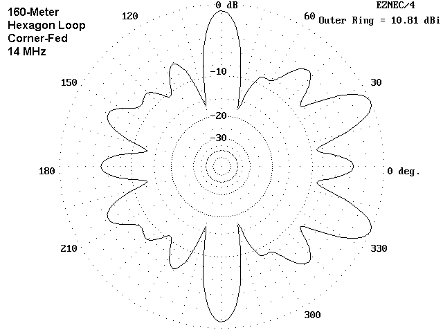
The 20-meter patterns for the larger loop show a combination of most of the pattern characteristics we have already seen: bi-directionalness, merged lobes, and a number of others. Primary radiation is off opposing sides, as with the 40-meter patterns, but with a greater complexity of lobe structure. As well, the feedpoint resistance and reactance values are fairly high.
Of interest is the fact that maximum gain values fall only in the middle of the span of those exhibited by the 80-meter loop when run at 14 MHz. On this band--and on others as well, the antenna offers little to justify the added complexity of running a wire twice as long as the 80-meter loop. One might well argue for some installations that the benefits derived on 80 meters from the larger loop are offset by the disadvantages on some of the higher bands. Indeed, the shorter loop and a separate 80-meter antenna might be easier to use.
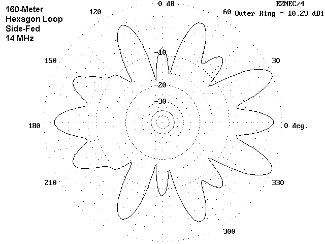

The 17-meter patterns for the 160-meter loop bear a striking resemblance to those for 40-meter operation if we do two things. First, we have to smooth the peaks of the narrower and more numerous 17 meter lobes. Second, we have to notice the movement of the peak gain regions a small angular distance away from their axes on 40 meters so that a narrow weak area develops along the precise axes of 40 meter peak gain.
As curious as the patterns are, the 17-meter impedance values are also interesting because they come closer to resonance than the values on any other band. However, there will still be considerable excursions of voltage and current on the feedline, because the high values of feedpoint impedance on other bands almost dictate the use of 600-Ohm open parallel feeders as the best compromise among all the impedance levels encountered.

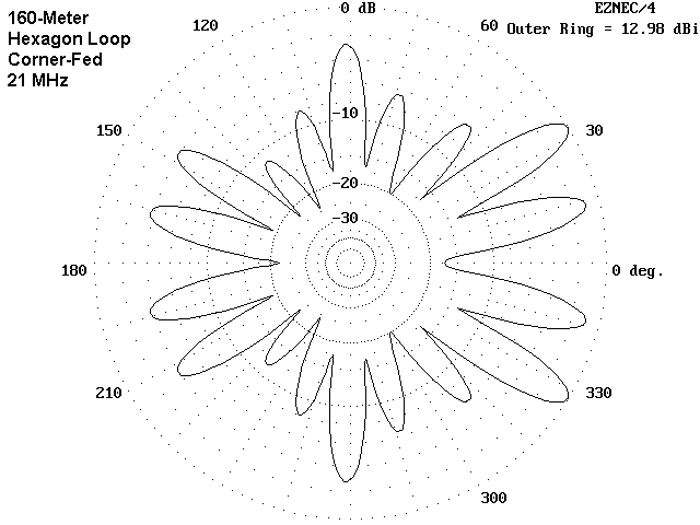
At a certain level of lobe multiplication, azimuth patterns tend to lose their identify as guides to antenna radiation and become more like Rorschach ink blot tests. With the 15-meter patterns of our large loop, we may have reached that stage. Local ground clutter, terrain irregularities, and simple blowing of the antenna wire in the wind may lessen the utility of following out each pencil-thin lobe of the azimuth pattern.
Nonetheless, we can gain something from observing the azimuth patterns, if only by gaining a general impression of regions of strength and weakness. For example, between the corner-fed and the side-fed patterns, the former seems to have more lobes of higher strength in more directions, thus promising contacts in both the morning and the evening hours of the daily skip cycle (assuming that the antenna is set up on a rough East-West axis).

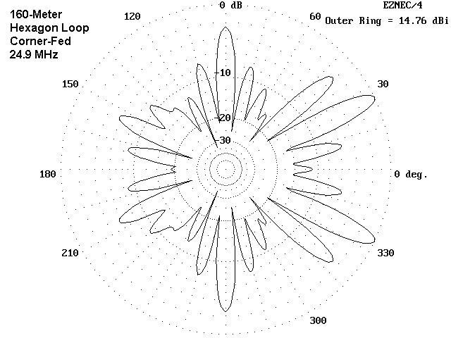
The patterns for both 12 meters and 10 meters share some interesting characteristics. Regardless of the feedpoint, there are very few lobes that are less than 8 to 10 dB down from the peak gain lobes, and almost all of them have very narrow beamwidths. Therefore, the effective gain of the antenna is not given by the maximum gain figures, which happen to range in the vicinity of 14 to 15 dBi. Rather, the average gain over the 360° horizon is more like 5 to 8 dBi. These are gain values more akin to a multiband quarter-wavelength vertical with a ground plane mounted on a roof top than they are to typical gain antennas.
There is a strong possibility that, if your interests are in upper HF operations, the large 160-meter loop will prove to be a disappointment. Its true virtue lies in the lower HF region, especially on 80 meters, with reasonable good performance through 20 meters.


Although the 80-meter loop shows poor performance on 80 meters for every application other than NVIS, the smaller loop has distinct advantages over the larger loop on almost every other band. The patterns are smoother, with reasonable gain in most directions. The feedpoint impedances are moderate and amenable to the use of inexpensive and readily available 300-Ohm or 450-Ohm parallel feedlines. The values of impedance presented to antenna tuners are more likely to be within the adjustment range of inexpensive units.
Size alone, then, is not the sole determinant of HOHPL performance. Smaller can be better for some operational purposes. As important as size is the antenna shape and the feedpoint position in the determination of the antenna patterns that will most benefit our operational needs. A HOHPL that best fits our needs is a blend of many factors.

80-Meter Square Loop, Corner-Fed:  Fig. 11

Freq.   Gain 	TO   	Feedpoint Z
 MHz 	dBi  	Deg  	R +/- jX Ohms
3.5     4.4 	45*  	120 - j 100
7     	6.0 	43    	95 - j 230
10.1 	10.4 	29   	280 - j 650
14      11.3 	20   	245 - j 240
18.1 	14.1 	15   	375 + j 245
21      14.2 	13   	250 - j 170
24.9 	14.7 	10   	345 + j 125
28      13.7  	9   	260 - j 220

80-Meter Square Loop, Side-Fed:  Fig. 12

Freq.   Gain 	TO   	Feedpoint Z
 MHz 	dBi  	Deg  	R +/- jX Ohms
3.5     4.3 	45*  	120 - j 100
7     	6.7 	37   	290 - j 105
10.1  	8.0 	27   	280 - j 610
14      10.7 	19   	215 - j 265
18.1 	11.7 	15   	415 + j 210
21      10.8 	13   	410 - j 215
24.9 	11.7 	11   	380 + j  20
28      12.2  	9   	280 - j 250

80-Meter Octagon Loop, Corner-Fed:  Fig. 13

Freq.   Gain 	TO   	Feedpoint Z
 MHz 	Bi  	Deg  	R +/- jX Ohms
3.5     4.3 	45*  	135 - j  55
7     	6.3 	41   	205 - j 150
10.1  	7.9 	29   	250 - j 580
14      9.3 	21   	155 - j 250
18.1 	11.6 	15   	310 + j 250
21      11.9 	13   	275 - j 230
24.9 	10.5 	11   	300 + j  40
28      11.4 	10   	310 - j 310

80-Meter Octagon Loop, Side-Fed:  Fig. 14

Freq.   Gain 	TO   	Feedpoint Z
 MHz 	dBi  	Deg  	R +/- jX Ohms
3.5     4.3 	45*  	135 - j  70
7     	6.3 	41   	200 - j 180
10.1  	7.7 	25   	250 - j 610
14      9.8 	19   	270 - j 230
18.1  	9.8 	16   	295 + j 150
21      10.0 	14   	275 - j 335
24.9 	10.8 	11   	265 - j  70
28      11.8 	10   	300 - j 415

160-Meter Hexagon Loop, Corner-Fed:  Fig. 15

Freq.   Gain 	TO   	Feedpoint Z
 MHz 	dBi  	Deg  	R +/- jX Ohms
3.5     5.4 	49   	145 - j 265
7    	10.5 	36   	350 - j 505
10.1 	10.9 	23   	2810- j 1140
14      10.8 	21   	815 - j 1010
18.1 	13.2 	15   	415 - j  90
21      13.0 	14   	1830- j 370
24.9 	14.8 	11   	870 - j 540
28      14.9 	10   	1300+ j 635

160-Meter Hexagon Loop, Side-Fed:  Fig. 16

Freq.   Gain 	TO   	Feedpoint Z
 MHz 	dBi  	Deg  	R +/- jX Ohms
3.5     5.5 	48   	145 - j 260
7     	9.2 	33   	285 - j 495
10.1  	8.9 	25   	2205- j 1105
14      10.3 	18   	655 - j 920
18.1 	11.7 	15   	385 - j 130
21      12.5 	14   	1570- j 687
24.9 	15.0 	11   	735 - j 585
28      14.6  	9   	1455+ j 125
Notes:
1. * beside a TO entry means that the angle used is arbitrary. Maximum gain is straight up (elevation angle = 90°).
2. Feedpoint impedance figures are representative and will vary with the exact length and layout of the antenna loop. The impedance presented to the antenna tuner will also be a function of the exact length, characteristic impedance (Zo), and velocity factor (VF) of the transmission line used for each particular installation.
3. Gain figures represent the maximum gain of the strongest lobe in the azimuth pattern and should not be interpreted as the sole basis for deciding among HOHPL designs. Equally important are the distribution of the lobes, the depth of the nulls, access to all desired communications directions, and other factors.
4. TO angles are the elevation angles of maximum radiation from the strongest lobe. The vertical structure of lobes may vary.

On 80 meters, there is no major difference between the doublet and the square HOHPL. The HOHPL shows a higher radiation angle, giving the doublet about 1.2 dB more gain (5.6 vs. 4.3 dBi at the arbitrary 45° elevation angle).

There is a distinct difference between the HOHPL and doublet 40-meter patterns. The doublet is 1þ long and shows a bi-directional pattern. The HOHPL loop is 2 wl long and displays major lobes in four directions, although at lesser gain (8.1 vs. 6.7 dBi at about 36° elevation). Which antennas has the advantage depends on one's operating needs.
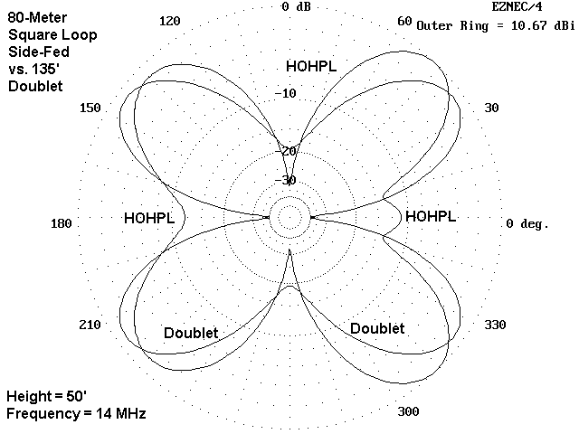
On 20 meters, the 1wl HOHPL shows enough tilt in the pattern away from the feedpoint to give it a small gain advantage at similar elevation angles. Although the patterns seem otherwise fairly similar, with only small offsets in the lobes, the doublet shows some deep nulls broadside to the antenna, nulls that can adversely affect communications in certain quadrants. Although the "side" nulls of the HOHPL are deep, they do not differ as much from the doublet wire-end nulls.
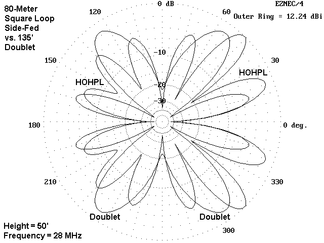
The 10-meter patterns, while a bit confusing at first sight, also show that the HOHPL has somewhat fewer nulls of great depth than the doublet. Moreover, especially in the direction away from the feedpoint, the HOHPL lobes are stronger (by about 1.5 dB) and more even in gain. In contrast, the doublet is beginning to show greater strength in lobes that are further from the broadside direction and more towards the antenna ends.
As a consequence of this behavior, the advantage of the HOHPL will not show itself in any one contact or in a short period. Satisfaction with the antenna grows with time and changes in the propagation paths, a successful communications almost everywhere shows up in the log.
Still, the HOHPL, even in its smaller 1 wl form, requires a considerable investment in real estate, supports, wire, and accessories compared to the simpler doublet. Only the potential user can decide if it is the right antenna for his or her installation. If it is, then in about a year, you will be able to scan your log and chuckle the famous chuckle:
Updated 1-19-99. © L. B. Cebik, W4RNL. Data may be used for personal purposes, but may not be reproduced for publication in print or any other medium without permission of the author.