 No. 27: A Compact Aluminum Moxon Rectangle

I often receive inquiries from folks who cannot quite support the width of a 10-meter Yagi (either 2 or 3 elements) because obstructions give them less than the 16.5' needed. Is there an antenna with decent performance that will fit in a space about 12-13' wide? If it can be home built to save money and require no fancy tuning or matching system, so much the better.
In fact, there is an antenna that fits this category almost perfectly. Imagine an antenna with the gain of a 2-element Yagi (6 dBi), the front-to-back ratio of a 3-element Yagi (>20 dB from 28.3 to 28.5 MHz), and an SWR of below 2:1 from one end of 10 to the other. In fact, imagine that the antenna has better than 15 dB front-to-back ratio all the way down to 28 MHz and still has about 12 dB front-to-back ratio at 29.7 MHz. (All figures are free space modeling estimates.) Imagine also that the antenna can be directly connected to 50-ohm coax with no matching system whatsoever (even though I always recommend a 1:1 choke balun). Imagine also that you can make it yourself from hardware store materials, that it will weigh about 10-15 pounds including the boom, and that you can make it in your garage with no special tools. Imagine also that when it is done, you will still have change from a $50 bill.

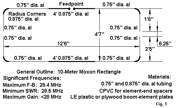
The antenna is the Moxon rectangle. Past versions that I built using wire elements required lots of PVC to support them. However, if we translate the antenna into hardware store aluminum tubing, we can build a 1-boom version. Now peak at the sketch of the pieces in Fig. 1. Some 7/8" and 3/4" diameter aluminum tubing form the main elements, with 3/4" tubing for the side elements. The corners can use radius-bent tubing or be squared by making some corner supports from L-stock. The combination of 7/8" and 3/4" aluminum tubing lets you telescope the ends into the center for a precise fit or a center frequency adjustment.
Since the end spacing and alignment is critical to make the antenna give its full performance, you can slide a piece of CPVC or similar lightweight, durable tubing either inside the ends or over the ends and lock them in place with sheet metal screws. The rigid spacer is also a good idea to limit the twisting force placed on the curved or right-angle corners. Sheet metal screws also connect the 3/4" and 7/8" tubing together. Be sure that all hardware screws are stainless steel.
For element-to-boom plates, you can use any durable material. Spar varnished 3/8" plywood or 1/4" LE plastic make good plates. About 3" by 9" (or longer) plates give ample room to U-bolt the elements to the plate and have room for U-bolts that go over the mast. As with all good antenna structure, let the elements hang under the boom. What boom? Well, almost anything, from 1-1/4" nominal diameter PVC to a good grade of aluminum tubing (thicker-wall than the usual 0.55" hardware store variety) to a 5' length of spar varnished 1.25" diameter closet rod. Make up a boom-to-mast plate similar to the boom-to-element plates, only a bit more square, and you are in business.
The dimensions of the antenna in the drawing are too fussy, being direct translations of the computer model used to generate the antenna. Just try to keep the dimensions within about 1/4" of the drawing, and no one will be able to tell any difference in performance. Squaring the corners or missing the dimensions by a half inch will shift the performance centers by about 100 kHz at most. In most cases, you will not be aware of any difference at all.
Note that the antenna is just about 12.5' wide and under 5' front-to-back, for a turning radius of about 6'8" or so. Strapped up on the side of the house, the antenna is unlikely to overhang the neighbor's yard line. The antenna is light enough for hand rotating, but an old TV rotator might come in handy. Because of the antenna's characteristics, you may not need to rotate it much.

The pattern figure shows the optimal front-to-back ratio in azimuth patterns 20' and 35' antenna heights. Note the very broad forward lobe that is almost a cardioid, giving reception and transmission as wide as your peripheral vision. Behind you is silence--or at least a large dose of silencing. Les Moxon, G6XN, uses a wire version of the antenna with both elements remotely tuned: that way he works the world just by electrically reversing front and rear elements with a fixed mounting. If you want to learn more about the Moxon rectangle, find the Spring, 1995, issue of Communications Quarterly, and look at pages 55-70.
It is unlikely that anyone will ever produce this beam commercially, since it is a monobander without the super gain that avid DXers and contesters crave. You can only get that kind of performance from many Yagi elements. However, you can build your own compact antenna with a pretty good chance of success on the first try. It will beat a fixed wire dipole or a vertical hands down. So if you need a compact 10-meter beam for your compact home site, then you might roll your own version of the aluminum Moxon rectangle.
For further details on the construction of this antenna, see The ARRL Antenna Compendium, Vol. 6, pp. 10-13.
Updated 3-12-2000. © L. B. Cebik, W4RNL. Data may be used for personal purposes, but may not be reproduced for publication in print or any other medium without permission of the author.