 No. 18: The Simplest 3-Element Yagi?
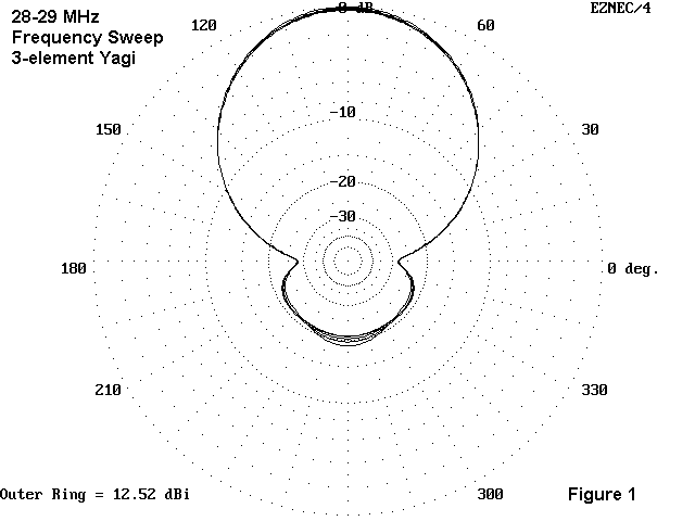
This beam has two essential items for the casual home builder. First, the antenna has a 50-ohm feedpoint impedance with a wide SWR bandwidth. In fact, the SWR stays below 1.4:1 up and beyond 29 MHz when the antenna is modeled for 28.5 MHz. Second, the characteristics (gain, front-to-back ratio) are almost constant for the entire first MHz of 10 meters. The gain ranges from 12.3 to 12.5 dBi, while the front-to-back ratio remains better than 18 dB across the band. Figure 1 is an azimuth plot of the antenna taken every quarter MHz from 28 to 29 MHz at a 35' height. The differences from one line to another are too small to make any difference at all.

For these benefits, there is a price to pay: lower gain. From a 3-element Yagi on a 12' boom, one can squeeze out another dB of forward gain and improve the front-to-back ratio by a couple more dB. However, these beams have two disadvantages for the home builder. First, they have a narrower bandwidth where these properties show up. Beyond certain frequency limits, the pattern begins to deteriorate. Second, the feedpoint impedance tends to be very much lower--in the 20-25 ohm range. The lower feedpoint impedance requires a matching network. Although adjusting matching networks can become routine, the process can take the pleasure out building one's first beam that works.
Let's go ahead and build one of these wide-band specials. First, we need some dimensions. Figure 2 supplies the data.

For 10-meters and simple installations, hardware store tubing is convenient and accessible. 1" aluminum tubing comes in 8' sections at most hardware depots. You will need 6 pieces, plus a shorter length of 7/8" tubing. You will also need a boom 12' long. One trick I have used is to take two pieces of 6' long 1.5" diameter aluminum tubing and lay them end to end. Now take two lengths of 1 3/8" tubing (or 1.25" if the larger tube is not available). Cut one smaller tube size length in half. Slide 3' of the 6' length of the smaller tubing inside one end of the larger tubing and fasten with stainless steel sheet metal screws. Slide the other piece of large tubing over the exposed 3' of smaller tubing, and fasten. Now slide the 3' lengths of the smaller tubing inside each end of the 12' boom, and fasten (but in such a way as not to interfere with the element mounting to come). We now have a 12' boom adequate for this simple beam.
Now make up 3/8" plywood plates about 6" wide and 3' long. coat them well against the weather. You can taper the pieces outward from the center to save a few ounces of weight. Find stainless steel U-bolts that go around the boom and around the elements. Let the plates go below the boom, and the element go below the plates.
Notice that two of the elements require aluminum pieces that are longer than the twin 8' sections of tubing we bought. Likewise, from the director, we shall cut off short section of tubing. Save them. For the reflector, set the tubes to the required extension. Take a 3' length of the 7/8" diameter tube and slide it inside one of the 1" diameter elements and fasten with sheet metal screws. Now slide either or both pieces of remnant director tubes over the 7/8" tube and position them so that they fit under the inner U-bolts. Again, fasten them to the 7/8" tube with screws. Now slide on the other 8' reflector section and fasten. The short segments of exposed 7/8" tubing will make no significant difference to antenna performance. (If you are a perfectionist, you can purchase one extra section of 1" tubing to make the reflector 1" in diameter for its entire length.)
Since the director only requires trimming to specification and mounting with a pair of U bolts on each side of the plate, the last item of concern is the driven element. Mount the element leaving a 6" space at the center. Slide 18" sections of 7/8" into each 1" tube and bring the ends close together. (The perfectionists can cover the exposed 7/8" tubing with short lengths of 1" tubing for a uniform driven element.) Fasten loosely and begin thinking about a boom-to-mast mounting and a coax connection. A small plate with a coax connector and the shortest possible leads to the antenna elements takes care of the connection. I like to use a 1:1 choke balun of W2DU design (ferrite over a length of coax), and this can be taped to the boom.
Mount the antenna about 10' off the ground pointing straight up. Adjust the driven element for resonance. Now get the beam up about 35' and begin waiting for sunspots.
This beam has only one more element than our 2-element special, but it is twice as large and twice as ungainly with its 12' boom. However, its performance improvement over the 2- element Yagi will show up instantly--or as soon as there are some folks to work. You will notice the effects of the added gain and front-to-back ratio on your local net. The bill will come to about $75 or so, which is not bad, if you have priced commercial beams lately.
There are beams with higher performance figures, but none any
simpler to build than this wide-band special.
Updated 2-21-98. © L. B. Cebik, W4RNL. Data may be used for personal purposes, but may not be reproduced for publication in print or any other medium without permission of the author.