 No. 14 EDZs: Stacked and Unstacked
After an article on EDZs (extended double Zepps) appeared in Communications Quarterly in Fall, 1995, I received some mail and phone calls on a version of the antenna I had not covered. So I thought I would bring it to your attention. The EDZ is a good fixed wire antenna for those who do not wish to fool with towers and rotators, but do wish to work some DX when the band fully reopens. It helps to have high trees or other tall poles to support the ends, and you have to like ATUs (antenna tuning units or transmatches). Even if you do not like these things, read on--they can grow on you.
At 10-meters, an EDZ up 40' in the air shows about 3.5 dB gain over a dipole. Of course, both antennas are bidirectional. The EDZ gets its gain by shrinking the side-to-side beamwidth of its two main lobes. The dipole has a half-power beamwidth of about 78° while the EDZ cuts that to about 30° with two small side lobes in each direction. See Figure 1
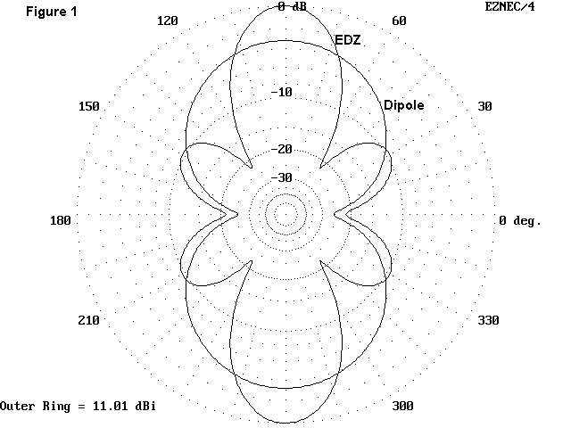
Some folks view the sidelobes as QRM producers. If you agree, see the ARRL Antenna Compendium, Vol. 4 for an EDZ with capacitors in the elements to eliminate them. However, you may lose some performance of the antenna on other bands.
Almost any wire antenna for 10 up in the air 40' has a take-off angle of 12° above the horizon. Take-off angle means the elevation of the lobe with the most power in it. The half-power points are ±6° around that angle, so there is plenty of power in the low angles needed for efficient DXing. But perhaps we can do a little better.
A vertical spacing of 5/8ths of a wavelength is about the most efficient gain producer when stacking antennas. This applies to Yagis and other arrays as well as EDZs. At 10 meters, this means a spacing of about 22' or so. Again, this number is not critical ±a foot. Figure 2 shows the general scheme. Assuming you have the side supports, there are only a few questions to ask about stacked EDZs.
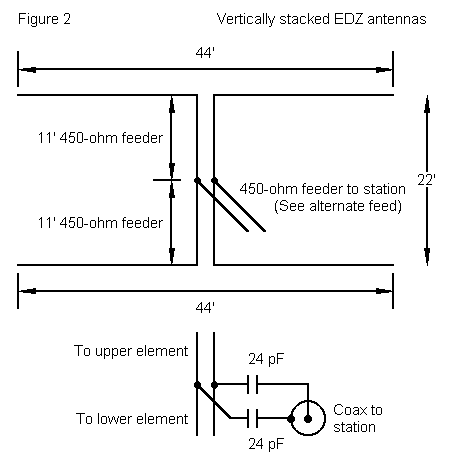
1. What do I get for my trouble? First, you get 3 to 4 dB additional gain in both directions, depending upon which wire you set at the 40' level, where we placed our one-wire EDZ. If you can put the second wire at about 60' or so, you will get the higher gain, plus a lower take-off angle of 9°. That puts the bulk of your power in the 10-meter far-DX zone. Figure 3 also shows a secondary lobe at about 28° for shorter paths. If you place the lower wire at about 20' up, you will get the lower gain and a basic take-off angle of 14°. That is still worth while.

2. How do I aim single and stacked EDZs? With care, since they are fixed. In much of the US, the NE-SW corridor gets you both Europe and VK- ZL-land. Or you can broadside N-S for South America and over-the-pole and back scatter. Or, you can broadside to Asia. Finally, if you have lots of trees or poles, you can build 3 EDZ stacks and switch among them (a nice wiry dream).
3. How do I feed the beast? The easiest feed system is to run 450- ohm parallel feeders from each feedpoint to a common center. At that point, you will see something like 75 ohms resistive and about 460 ohms inductive impedance. This situation gives us a choice.
a. If you wish to use the antenna on 10 meters only, you can insert on each side of the line junction a 24 pF capacitor. This is a series connection on each side, with the ends then connected to each side of a coax connector. The capacitors cancel out the inductive reactance, leaving only about the same mismatch you would get with a dipole--and that's manageable.
b. If you wish to use the antenna on all bands from 20 meters on up, just connect more 450-ohm parallel feeder and bring it to the shack and ATU. On 20 you will get dipole gain or better, with more gain on the other bands between 20 and 10.
4. What does it cost? Well, #14 wire runs about 7 to 12 cents a foot, depending on its nature, and 88' of wire is in the $8.00 range. Add some insulators and rope for supports. Then add the 450-ohm parallel feeder, which is cheaper than coax. Even if you have to erect some supports (4 sections of 10' TV mast per side, plus rope guys and tie-down ring-screws in the ground), you might run the bill to $75 to $100. That will barely buy the TV rotator, let along the tower and very light beam that goes with it.
Note that, as in all antenna work, we must compromise. The stacked
EDZ requires supports and fixes your general directions to two, but saves
you many dollars, pounds, yen, francs, marks, or lire. The long Yagi with
the same gain gives you freedom of direction, but empties your pockets and
requires constant maintenance. (Remember, Murphy's law says that when the
rotator goes bad, it is always stuck in a direction with no hams in sight.)
So the EDZ and the stacked EDZ array are suitable only for some people.
But perhaps you are one of them.
Updated 4-23-97. © L. B. Cebik, W4RNL. Data may be used for personal purposes, but may not be reproduced for publication in print or any other medium without permission of the author.