 No. 10 Notes on 10-Meter Antenna Tuners
There are many excellent antenna tuners (ATUs) on the market that will match at 80 or 160 meters. On 10, the match may be more of an illusion than an effective reality with some designs. If you are a dyed-in-the- wool 10-meter operator and use an antenna system that calls for an antenna tuner, you may be better off building your own.
So what is wrong with the commercial tuners? (Remember, not all of them are wrong. Compare the points made here with the features you see when you think about buying one.) A number of things go wrong in designs aimed at covering 160-10 meters.
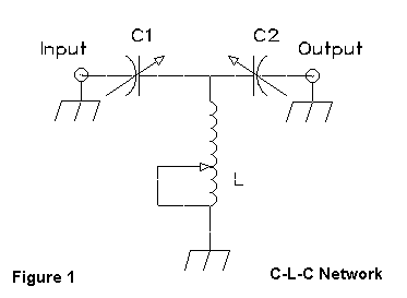
1. The basic design: Most ATUs use a T-network with series capacitors and a shunt inductor, as schematically shown in Figure 1.

This design is a high-pass filter and provides little, if any, suppression of harmonic energy. One can argue that we should not rely on the ATU to do the job our rig's output circuitry should be doing. That argument is sound, but if there is a design that will also provide some harmonic energy suppression, it may be preferable. Two designs fill the bill.

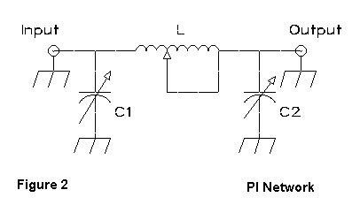
Figure 2 shows a PI network with shunt capacitors and a series inductor. It is inherently a low-pass filter.

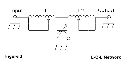
The circuit in Figure 3 is also a high-pass filter: it is a T-circuit with series inductors and a shunt capacitor.
The reasons for using a series-C T are cost and size. The components for it are smaller for a given power level, since we can fit a 20+ microH coil (rotary or tapped) alongside a pair of 250 pF variable capacitors in a compact case. By contrast, the inductors for the other circuits may require up to and over 30 microH, and the capacitor for the series-L T may need values up to 1000 pF. That is, if you want to tune 80 or 160.
If you only want 10 meters, then the values drop. A 5 microH inductor (or 2) and a 250 pF air variable (or 2) give all the range anyone should need for 10.
2. Tapped inductors: A tapped inductor may do the job you require, but for some antenna situations, you may not be able to find the 1:1 SWR point. That is not fatal if you can find a point under 2:1. However, a good rotary inductor (or 2 in the series-L T circuit) is superior, since there is no required setting that is unavailable to you. You can find some good near bargains in rotary inductors at hamfests. The same applies to capacitors.
3. High-value components: The higher the highest value of a capacitor or coil, the higher the lowest value. The large frames of high-value rotary inductors may limit the lowest value to well over 1 microH. Capacitors are even worse, because the high maximum value does not tell the whole story. Usually, capacitors follow the rule, but you also have to watch out for construction. I have an old military capacitor with a maximum value of 35 pF. Unfortunately, its lowest value is 17 pF. It is built within a set of frame plates that surround the stators and limit how low it can go. By contrast, a 100 pF old E. F. Johnson capacitor in one of my units has a minimum value of about 10 pF. Its supporting metal work consists of two small plates on either end of the unit. If you roll your own, look for the capacitor's minimum value as well as its maximum value.
4. Closed tight cases: On ten meters, some commercial ATUs achieve a match more with stray capacitance and inductance than with the higher Q variable components that are supposed to do the work. Steel cases that cut the inductive fields of coils and provide several pF of shunt capacitance to the other components complicate and usually hinder the basic work of the matching network. A spacious case, however much against the grain of today's stylistic fetish of ultacompactness, is a plus for an ATU.
5. Poor ground paths: Ideally, there should be one good ground point for the ATU network. With large components, this condition is often impossible to attain. However, grounding should be as direct and compact as possible--and as near to the ground lugs of the coax sockets as possible. It should not rely on the bite of a lock washer through a painted surface. A rivet used as a ground connector is a prelude to malfunction. There are no shortcuts to good, short, wide ground paths and good mechanical and electrical connections. They are not expensive, but they do take care.
This list of difficulties is not an indictment of all ATUs. Many units have taken the trouble to be the best they can be as 80 or 160 through 10 meter units. However, you can probably do better yourself. For 10 (or realistically, 10-20 meters), a PI or series-L T circuit is achievable with parts you can obtain from hamfests. A PI might use a 5 to 10 microH inductor with a pair of 250 pF air variable capacitors of good power rating. A series-L T circuit might use a pair of 5 or 10 microH rotary inductors and a couple of 250 or 300 pF variable capacitors, with a switch to bring them into play either one or both at a time. A surplus or home brew case with plenty of room helps ensure that strays are minimized, as do well-planned ground paths. Consider a plexiglass case for the ultimate in avoidance of strays.
Remember, multiband is not always the most efficient, even if it is
the most compact. The bands that take the beating are the ones at the high
and low ends of the multiband range. Ten meters, unfortunately, is one of
those ends. Hence, if you use a 10-meter antenna system calling for an
ATU, consider building yourself a customized unit with all the advantages
and none of the difficulties.
Updated 3-17-97. © L. B. Cebik, W4RNL. Data may be used for personal purposes, but may not be reproduced for publication in print or any other medium without permission of the author.