Placing sources and loads precisely can be more work if they do not happen to fall at the center or end of a wire. How can we place them with high precision relative to an existing or proposed antenna?
There are a few techniques that work very well, although some of them have attached pitfalls that we would want to avoid. We can illustrate the techniques if we contemplate a hypothetical problem demanding great precision. For most of us, the problem will be somewhat unreal, but we will not let that get in the way of seeing how the techniques of source placement work. In this episode, we shall look at sources only, reserving loads and their special requirements for next time.
Consider a wire antenna for 3.5 MHz made up of #14 AWG copper wire. The antenna will be at 70' above average soil. (For modeling purposes, NEC models were run over the high-accuracy Sommerfeld-Norton ground, which is not available in public-domain MININEC 3.13. The 70' antenna height places the antenna about 0.25 wavelength above ground, within the accepted limits for MININEC. However, in this area of transition, some variance in the resonant length of antenna is to be expected between NEC and MININEC.)
If this 80-meter antenna were a standard center-fed type, we would simply place the source in the center. With MININEC, this requires an even number of segments; with NEC we need an odd number of segments. If we further suppose that we want to resonate the antenna so that the source impedance showed less than +/-1 Ohm reactance, we would simply adjust the total length until we achieved this goal. If we set the source at the 0,0,70 point, with equal wire lengths extending to either side of this point, then we would play equally with two end values, but keep them equal to each other.
This is the standard easy case. So lets make the problem a little harder. Suppose we want our wire to be about a half wavelength long, to be resonant within an Ohm or two, and to have the source placed at the point where the resonant impedance is 300 Ohms. Granted, for building purposes, something close to this would do fine, but remember that we are (for some unspecified project reasons) demanding precision.

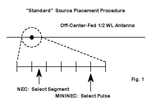
If your program allows, you can approximate the 300-Ohm feedpoint by moving the source off center, as shown in Figure 1. In MININEC, we select a pulse number, which is always at the junction of two segments. In NEC, we select a segment and visualize the source as being at its center. Of course, we use sufficient segments in each case to ensure convergence.
To get ahead of myself, I shall specify that the NEC antenna is 136.55' long. Because uncorrected MININEC does not correlate perfectly with NEC, the MININEC antenna will be 136.01' long. These lengths are based on using one of the techniques to come, but for the moment, let us just accept them. Remember also that different implementations of both NEC and MININEC may return slightly different values, based on a host of reasons related to input and output operations, rounding, and other similar factors.
Since we are trying to be precise, let us choose 136 as the number of segments for our MININEC antenna and 137 segments for the NEC antenna. This move yields segments about 1' long for the two antenna, each segment being about 0.0036 wavelength long, well within limits for each program.
In MININEC, if I place the source at pulse 23, it is 16.91% in from one end (just about 23.0'). The source impedance report is 317.50 - j1.91 Ohms. Again, this precision is excessive for most practical purposes, but for this example, the numbers will show some things about both the models and the programs. If I move to pulse 24, then the source is 17.65% in from one end (about 24.0'). The impedance report is 295.37 + j1.62 Ohms. Pulse 24 is close to the goal. Moreover, the antenna is close to resonance, and we would expect that the 300-Ohm point to show under 1 Ohm reactance. So we might well estimate the "true" 300-Ohm source point at about 23.6 to 23.7 feet in from one end. However, unless we were to be very lucky in resegmenting the antenna to find a pulse very close to that point, we cannot get more precise.
The case with NEC is similar. Using segment 24, we get a source that is 17.15% in from one end or about 23.42 feet (remembering that the NEC antenna model is not the same length as the MININEC model). The source impedance report is 314.3 - j3.32 Ohms. Moving to segment 25, which is 17.88% in from one end or 24.42 feet, we find 292.9 + j0.18 Ohms. The 300- Ohm point is between the two, perhaps at about 24' in from one end. Moreover, we might expect it to show something over 1 Ohm capacitive reactance. Again, we can juggle segmentation and hope to hit the mark.
Surely there must be an easier way. In fact, there are at least two.

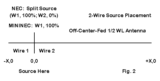
In MININEC, we shall initially let Wire 1 run from abut -23.6' to 0, with Wire 2 running from 0 to the +112.4' mark. We shall place the source on Wire 1 at the 100% mark, which forces it to the junction of the two wires. We shall leave our segment total at 136, with 24 on Wire 1 and 112 on Wire 2. The aim is to keep the segment lengths on the two wires roughly equal. We might reduce the number of segments on each wire to proportionately lower numbers for speed of running the model. However, the segment lengths might change more significantly if our first estimates prove to be somewhat off.
Now, by adjusting the end lengths only, we can establish both the 300-Ohm source impedance point and resonance within whatever limits we set for the problem. In fact, the model at hand required that Wire 1 be 23.78' long while Wire 2 had to be 112.23' long to yield a source impedance of 299.87 + j0.54 Ohms with a voltage source.
Selecting a voltage or a current source in MININEC yields identical source impedance numbers for center-fed (symmetrical) antennas--at least within the limits of the decimal places usually shown. When the antenna is not symmetrical with respect to the source, with identical segments lengths on either side of the source, moving between a voltage and a current source will show a slight, but normally wholly insignificant variance for any desired level of precision. The current source option yielded a source impedance of 299.96 + j0.73 Ohms for this model. The differential also appears to lessen the closer the model is to absolute resonance (for example, when the reactance reaches 0.1 Ohm). I note these phenomena, but repeat that the differential is insignificant in MININEC.
In fact, the two-wire method is the method of choice for MININEC modeling for precise source placement.
In NEC, the situation is somewhat different. For our 136.55' long antenna, we can set up the wires as we did for MININEC, with wire 1 having an end coordinate of about -24' and using about +112.5' for the end of Wire 2. The two wires meet at 0,0,70.
Placing the source for this antenna depends somewhat on the implementation of NEC that you are using. Some versions, such as EZNEC, permit placement of the source by specifying Wire 1, 100%, and choosing a Split Voltage source. The effect of this move is the same as setting up two sources, one on the last segment of Wire 1 and the other on the first segment of Wire 2. The program simply adds the two source impedances, which in other implementations, you might have to do manually.
For the model at hand, with 2 sources, the end coordinates for resonance and 300-Ohms proved to be -24.1' and +112.45' respectively. The source impedances returned were 152.4 - j0.45 Ohms and 147.1 + j0.36 Ohms. These total to 299.5 - j0.09 Ohms. (A split-voltage-feed option selection produced 299.5 - j0.06 Ohms as its report.)
Notice that the two impedances are not identical. Although close in length, the segment lengths for Wires 1 and 2 are not identical. Moreover, the currents on each side of the 0,0 point are also not identical, since the feedpoint is off center. If we choose a current source for this model, we should expect some variance from the voltage-source option, since the current source option is generated via a network. In fact, the 2-current- source option produced values of 32.3 - j760.1 Ohms and 259.1 + j734.4 Ohms, for a net impedance of 291.4 - j25.7 Ohms. For precision work, this result is considerably at variance from the voltage source models. In general, where such variations appear with NEC models, the voltage-source option is usually the more accurate.

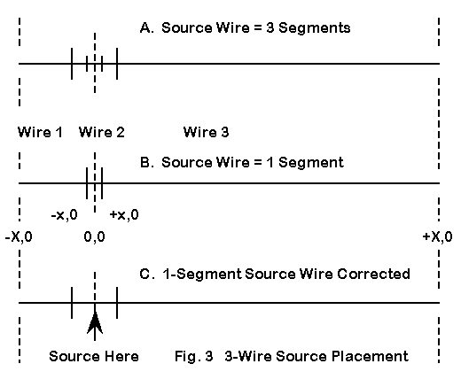
First, we shall set up Wire 2 by first settling upon a segment length and then centering a 3-segment wire length around the 0,0 coordinate. Since our model uses segment lengths of just about 1' each, we can set up Wire 2 as running from -1.5 to +1.5. Wire 1 then runs from about -24.1 to the junction with Wire 2. Wire 3 runs from the junction of Wire 2 to +112.45. Thus, we maintain our overall length of 136.55' for the antenna. (Note: once more, there is no rule that prevents the modeler from creating the wires from right to left. Nor is there any rule that requires the short end of the off-center-fed antenna to be on the left. My only suggestion is that, whatever conventions you use, you use them consistently in all similar models for the sake of ease of error detection and prevention.)
Wire 1 and Wire 3 are now shorter than formerly, so they should receive 23 and 111 segments respectively to hold segment length very close to the 1' mark. The total is 137 segments for the model. This arrangement corresponds to part A. of Figure 3. We place a single source of either type at the center of Wire 2.
The model reports a feedpoint impedance, using either voltage or current source options of 299.5 - j1.21 Ohms. The slight capacitive reactance is just what we expected based on our original estimates derived from the 1 wire model where we inspected the source impedance on segments that bracketed the 300-Ohm point.
One dangerous temptation of using the 3-wire method is first to arrange Wire 2 as specified and then to decide that the long wires can use fewer segments. Since the antenna is, overall, only about a half wavelength long, we might easily reduce the Wire 1 segmentation to 4 and the Wire 3 segment number to 19, a proportional drop. However, this move makes the segments adjacent to the Wire 2 segments 6 times longer than the segments in Wire 2. The source impedance now reported is 288.6 - j2.29 Ohms, a significant difference from the case where all segments along the wires are close to the same in length.
If we maintain equal segment lengths with all three wires, we can reduce the center wire to 1 segment and shrink its length to 1' by setting its coordinates at -0.5 and +0.5. This move is suggested in part B of Figure 3. Bringing Wires 1 and 3 to join this new Wire 2 calls for increasing their segment numbers by 1 each to 24 and 112, for a total of 137 segments. The source impedance reported for this model is 299.5 - j1.10 Ohms, the same for even the most critical purposes as the 3-segment wire 2 model produced.
However, the temptation to reduce the number of segments on the longer wires produces more radically erroneous results with a center wire having only one segment. If we retain the 1' center wire but decrease the number of segments on the end wires to 4 and 19 respectively, the model reports a source impedance of only 260.3 - 2.02 Ohms. Notice that the resistive component is far off the reliable mark, although the reactance has not changed significantly.
The segments of the end wires in our "temptation" model are about 5.7' long. We may retain this segmentation by increasing the length of the center wire to a like amount by setting its coordinates are -2.85 and +2.85. Then, with 4 segments to Wire 1 and 19 segments to Wire 3, the model reports an accurate source impedance of 299.5 + 0.76 Ohms.
If the smaller model yields reasonably accurate results, why use the highly segmented model? This fair question has a fair answer. With longer segment lengths, it is easier to develop inequalities of length without either knowing it or being able to correct the inequalities by the simple addition or subtraction of a segment here or there. With short segments, a growing inequality tends to show itself, especially if the lengths have a convenient correlation to the physical dimensions, as they do in this model sequence. Moreover, adding or subtracting a single segment from the end wires has a minimal impact on the length of each segment.
The 3-wire method of source placement is the most accurate and unambiguous for NEC. Moreover, using 3 segments in the source wire resists the effects of unequal segment lengths in adjacent wires more effectively than using only one segment in Wire 2, although the effects even on the 3-segment center wire can upset precision in some instances. As we noted in the beginning, these methods are applicable only where source placement needs to be as precise as possible.
I ran the same exercise, with a slight modification on MININEC, even though the 2-wire method is in its simplicity and accuracy the method of choice. For the exercise, the MININEC center wire had 2 segments to ensure placement of the source at the 0,0 point, roughly comparable to part A of Figure 3. In this case, the wire ran from -1.0 to +1.0, with the connecting wires reaching -23.78 and +112.23.
MININEC returned a source impedance report of 300.20 + j1.35 Ohms (compared to 299.87 + 0.54 for the 2-wire method). Leaving the center wire untouched, the segmentation was reduced to 4 and 19 on the end wires. The source impedance reported was 298.72 + j5.94 Ohms. Although MININEC shows more variance of reactance under these conditions than NEC, the overall MININEC impedance was considerably less affected by radical resegmentation than was that reported by NEC.
Returning the center wire to a suitable length relative to the segment lengths on the outer wires, MININEC reported a source impedance of 298.66 - j2.37 Ohms. As expected, the reactance is now closer to the value reported by the 136-segment model, although the resistive part of the impedance remains below the value reported by the more heavily segmented model.
In general, for this class of cases, MININEC is less sensitive than NEC to changes in wire segmentation for multiple wires making up a single antenna element.
Moreover, not all uses of antenna modeling software are directly geared toward either the construction of a proposed antenna or the analysis of an existing antenna. There are innumerable exercises one can perform with modeling software to understand better the operation of many types of antennas. For example, off-center-fed 1/2 wavelength antennas show interesting source impedance curves as the feedpoint is moved outward along the antenna. Moreover, the resonant length of the antenna changes with the feedpoint position and impedance. This is but one of a host of cases in which we can use our modeling software as a very effective self-instruction tool. The more we know about antenna performance in general, the more sense we can make out of the analysis of specific antennas and the more confidence we can have in the models we convert into real antennas.
In addition, when you pass the 1/2 wavelength mark in antenna size, there are ordinarily options in the placement of the feedpoint. A 1.5 wavelength antenna may be fed at its center or about 1/4 wavelength in from one end. These collinear arrays demand some precision in source placement not only as a guide to construction, but as well to understand the resultant radiation patterns.
The techniques we have explored here are also applicable to the placement
of various type of loads along an antenna element. What a reactive load
size needs to be, relative to typical antenna design goals, depends upon
precisely where along the antenna element we place it. Moreover, traps
require careful placement and design in order to be effective in an antenna
element. We shall find (next time) that the techniques of modeling source
placement explored in this episode have extensive application to the
precise placement of loads.