A good model does not begin at the computer, but on a piece of paper. Not just any piece of paper, but some kind of useful form on which you do all the the preliminary work so that you can just transfer the values into the program. (Given the variety of programs, transfer can mean typing up and saving an ASCII input file, entering values in screen tables and entry points, or entering values and selections into a spread-sheet form and pull-down boxes.)
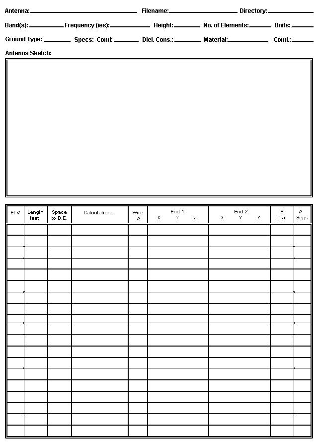
Figure 1 shows a form that I have used for a number of years for common HF and VHF antenna types. Although you can print out the form, you might want to make up your own crisper and more individualized form on a word processor.
Let's divide the form into 4 sections and see how it can help our model input work.
1. The header: The top lines of the form provide basic information about the model file and the background values within which the antenna will be modeled. The top line forces you to give the model a name--one that is either specific or generic--along with a file name and directory location. The last two items are important once you begin to develop collections of models. It is aggravating to lose ten minutes trying to remember where you stored a file.
The second line begins the modeling information. The band(s) entry allows you to specify one or more bands on which the antenna may be used, while the frequency entry is for either the antenna design center frequency or the upper and lower frequencies of a sweep you may intend to perform. The antenna height, even though it may be repeated in the wire table, is a reminder of the intended use of the antenna. Alternatively, if the model is preliminary, you may wish to enter "FS" for free space. Recording the number of elements is a check on the wire table entries below, which may consist of many wires. Recording the units of measure for the antenna elements can save you from trying to mix units later.
Recording the ground type and specifications (if other than free space) should be a standard part of your modeling practices. For horizontal antennas, such as dipoles and beams at HF, the use of a ground other than the usual program default may not make significant differences in the data produced by the program for the model. The default for most implementations of NEC and MININEC is "Good" or "Average" soil, with a conductivity of 0.005 S/m and a dielectric constant of 13. These values are taken ultimately from studies performed in the 1930s and often repeated in antenna handbooks.
Some programs provide some preset soil types, and the instruction manual will generally describe their values and characteristics--or refer you to the source handbook from which they came. However you obtain the ground values, be sure to enter them both here and in the program. These values are especially important for vertical antennas, whose performance may vary with either or both the ground type directly under the antenna and the ground type at a distance from the antenna. If you plan to use multiple grounds (for example, one in the immediate vicinity of the antenna and another at a distance), you might make an abbreviated entry here and develop the details on unused lines further down the form.
Modeling programs may specify the antenna material in one of two ways: either as a material type (such as "copper") or as a specific value. The program may call for either a conductivity or a resistivity value, where one is simply the inverse of the other. For example, copper has a conductivity of 5.8 E 7 (where "E 7" means "10 to the power of 7") S/m, which is equivalent to a resistivity of about 1.7 E -8 Ohms/m. (Some programs will still use "mhos/meter" instead of "Siemens/meter.")
As a modeler, you always have the choice to begin your modeling with zero-loss wire. However, it is usually good practice to specify the antenna wire material in terms of the actual material you intend to use (or are using) in order to take its distributed losses into account. In many cases, the differences between zero-loss wire and actual materials may make only insignificant differences in the output data. However, this fact will not be true for all antenna designs. In addition, some programs require a single material for the entire antenna, while others permit material or resistivity/conductivity specification on a wire-by-wire basic. If limited to a single material for some design combination of copper wire and aluminum tubing, you can choose the material that is quantitatively dominant in the design, the one most prominent near the high current regions of the antenna, or simply the one with the higher losses.
2. The antenna sketch: To get an understanding of the importance of sketching the antenna to be modeled, let's look at Figure 2, the data sheet for a simple 10-meter aluminum dipole.
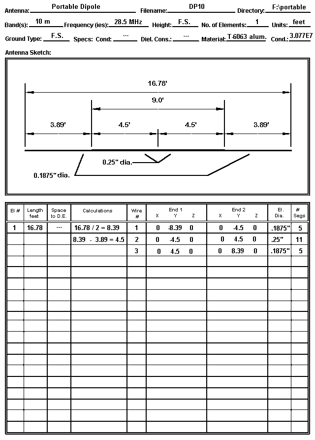
On this data sheet, the header is completely filled in with the basic and background data. Note that for this model, "Free Space" has been selected as the modeling medium. Note also that the material is 6063 aluminum, whose conductivity value may differ from other types of aluminum that might have been used.
The sketch itself should be (and this one tries to be) as complete as possible. Not only does the drawing show the overall dimensions, but as well, it displays the lengths and diameters of the individual sections of the dipole elements. Since each change of diameter represents the stop/start point for a wire in the model, complete dimensional data is necessary in order to correctly enter the wire geometry.
Although my CAD program has permitted me to overdo the graphical aspects of the antenna sketch, a pencil sketch will normally suffice. However, strive to make it as clear and complete as possible. Remember that it is the fundamental reference for all other modeling work you do.
3. The wire chart: NEC and MININEC operate on the basis of wires that are segmented according to rules. A single antenna element may consist of more than one wire, if the diameter changes along the way. In our simple example, we have two 3/16" diameter end pieces and a 1/4" diameter center section.
In reality, the center section may consist of 2 pieces of aluminum, slightly separated at a center feedpoint. However, the source (the feedline) is considered to be in series with the segment to which it is connected, and therefore, the wire should be continuous. You can accomplish this by specifying a single 1/4" wire and placing the source at its center. In NEC, you will select an odd number of segments for this wire to ensure source placement at the exact center. In MININEC, you will select an even number of segments to accomplish the same goal. Alternatively, you may choose to create two wires, one for each side of center. By placing a MININEC source at the end of one, it will be correctly placed where the other begins. In NEC, the same task requires selecting or creating a split feed to include the last segment of one wire and the first segment of the next.
In this model, I chose a symmetrical arrangement of the element, using the zero point as the center. I also chose to extend the element length along the Y-axis. Since the antenna has only length, the X-axis is always zero, and since it is in free space, the Z or height axis is also zero. (In most programs, the Z axis can be anything when modeling in free space, and you may want to enter for Z the height of intended use for the antenna.)
Selecting the Y-axis for the antenna length values over the X-axis may or may not be an arbitrary decision, depending upon the program you are using. Some programs, like AO, have a provision for increasing calculation speed via symmetry. If the antenna elements are centered--but only on the Y-axis--the program can calculate only half the antenna and treat the other half as a mirror image. This feature must be disabled for non-symmetrical antennas or for antennas whose length is specified along the X-axis.
In many programs, it makes no difference to calculation speed whether the antenna element lengths appear in either the X-axis or the Y-axis. In some programs, especially when surveying the wire length values of a very complex but linear antenna, it is more visually convenient to scan the left-most X-axis to check for errors. In the end, however, try to adopt one consistent convention for most--if not all--of your models. Swapping axes as you hop from model to model can be a source of unintended errors.
Among the most important conventions to adopt is to begin at one end of each antenna element and to proceed from that end to the other without changing directions in mid-stream. In the figure, note that the model proceeds from left to right along the sketch, symmetrically with respect to the zero-point of the Y-axis. Hence, a 16.78' antenna becomes +/-8.39' long.
Notice also that end 2 of the first wire becomes the starting point or end 1 of wire 2. For continuous antenna elements, be certain that the X, Y, and Z values of joined ends are the same. Some programs will indicate when wires are connected; others will rely on you to ensure that the junction ends have the same values. NEC connects wires that are within very tiny distances of each other, so also be certain that, if you do not want wires connected, they are far enough apart.
Wire entries also require that you specify the wire diameter. Many programs allow you to specify common American AWG wire gauges, which is useful for copper wire antennas. These are converted for the program into actual wire diameters. To be more precise, they are converted in the wire's radius. If you look at the NEC input file in programs that permit this, you will see the converted value of the diameter you entered in the input page or file.
You must also specify how many segments the wires will have. In order to make the segments for each wire reasonably close in length, the end wires in Figure 2 have 5 segments (0.78' per segment) and the center wire has 11 (0.82' per segment). Since the center wire containing the feedpoint (source) has an odd number of segments, it is clear that this model is intended for NEC rather than MININEC.
4. Source and other data: Missing from the form is any clear specification of the source or feedpoint for the antenna. (Actually, on my own forms, the source specification is on the reverse of the page, along with entry areas for loads, networks, and transmission lines--all subjects of future episodes in this series.) You can and should enter the source specifications on a spare line below the wire lines. For most antennas, this will place the data where it is most usefully compared with the wires themselves.
Enter not only the source location, but also the type (voltage or current, single or split) within the limits allowed by the program. We have already seen the utility of split sources. Single voltage sources are the native environment of most modeling programs. However, specifying a current source and giving it a value of 1 is often very useful for comparing current magnitude and phase output data for each segment along the antenna element(s).
This model is now ready for conversion into the appropriate program inputs.
Some Other Element Entry Considerations: In our fairly simple dipole entry, we had little difficulty in proceeding from element-end to element- end. However, some antenna designs may not make this process so simple in all cases.
Having examined numerous antenna models from a wide variety of sources, I am struck by the diversity of ways in which modelers create antenna elements and subdivide them into wires and segments. The variety of ways in which wires are placed into the antenna geometry descriptions often makes it difficult for another modeler to read the wires page. Moreover, many of the models will produce correct far-field data and feedpoint information, but will skew the antenna currents. This latter information can become quite important in analyzing why a complex antenna yields its particular set of performance outcomes.
The usual reasons given for the odd collections of wires making up an antenna model are convenience and speed. Many complex antenna element specifications are for half elements, starting at a boom or center point and moving toward the element tip. The specification presumes that other half of the element is a mirror image of the first. So modelers tend to begin in the middle and to work outward. Specification tables usually give the dimensions using positive numbers. Since it is faster to do the positive side, modelers then replicate that side and insert minus signs. Moreover, they tend top go directly from whatever sketch or data sheet they have to the screen entries. I have learned the hard way that slowing down at the beginning saves me a bucket of time later on when I try to troubleshoot my model.
Let me make some suggestions, scratched with chalk, not etched in stone. They began with my suggestion of always working from one end of the antenna element to the other end, and using the same directional sense for each succeeding antenna element.
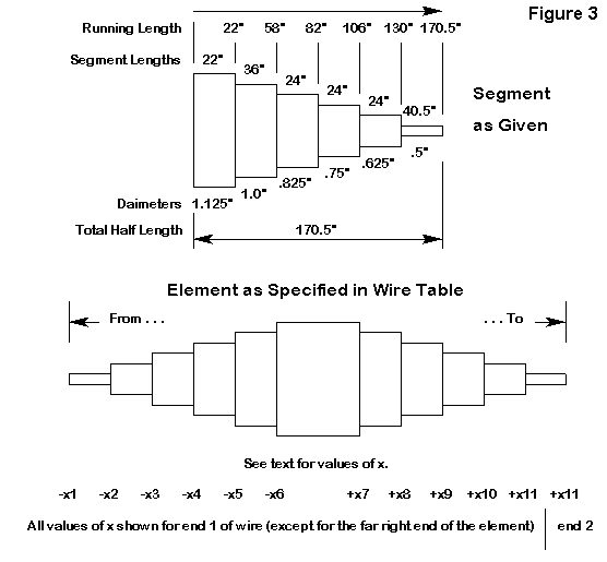
Now consider the element shown in Figure 3. It is one element of a multi- element Yagi. Each element uses many shorter sections of tubing that decreases in diameter as one moves outward from the boom to the end. Let's assume an element that from center outward has these dimensions: 22" at 1.125" diameter; 36" at 1"; 24" at 0.825"; 24" at 0.75"; 24" at 0.625"; and 40.5" at 0.5". The first step is to obtain running totals: 22"; 58"; 82"; 106"; 130"; and 170.5".
If we follow our conventions, the full element will look like this on paper and in the geometry entry spread sheet (noting that I have in this case chosen to place length values in the X-axis column):
Wire End 1     x         y    z    End 2     x         y    z    Diameter
 1             -170.5    0    0              -130      0    0     .5
 2             -130      0    0              -106      0    0     .625
 3             -106      0    0              -82       0    0     .75
 4             -82       0    0              -58       0    0     .825
 5             -58       0    0              -22       0    0     1
 6             -22       0    0              22        0    0     1.125
 7             22        0    0              58        0    0     1
 8             58        0    0              82        0    0     .825
 9             82        0    0              106       0    0     .75
10             106       0    0              130       0    0     .625
11             130       0    0              170.5     0    0     .5
(In some programs that permit symbolic entries, the numbers may be replaced by a set of variables indicated by a letter or combination of letters, with a list of values for these variables set out elsewhere.)
This process may seem like a long way to go, but for an accurate model, all these wires will have to be in the chart anyway. This left-to-right scheme just keeps them well-ordered. Note that wire 6 is the center section and can have the feedpoint specified at its center, with correct segmentation. For NEC, I might assign it 5 segments; for MININEC, 4. The sections with dimensions in the 20s might get 2 segments each, with the 36" section getting 3 segments, and the end sections 4 segments. This procedure keeps segments lengths as close to equalized as this structure permits, while holding the segments lengths well below maximum recommended length.
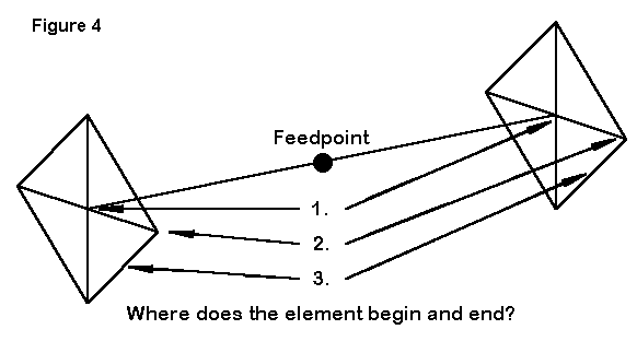
Now let's consider a second example: a shortened dipole with wire hats on each end. The hats consist of 4 radial wires and a perimeter wire. Where does the antenna element start and end? Some quick modelers use the horizontal dipole ends and then separately model the wire structures outward and around. However, the wire hat assemblies are part of the antenna. An equally quick second answer is to treat the peaks where the radial wires end as the antenna beginning and ending. Both answers are wrong. The antenna begins and ends where the current goes to zero. MININEC gives a true zero reading, because it takes current nodes to be at the ends of segments. NEC takes current nodes to be at the center of segments, and so the lowest value will never be zero. However, you can get equally low values either side of a correctly chosen wire junction.
For this example, the antenna begins in four places: at the center of each of the four perimeter lengths. It ends in the comparable places at the other end assembly. Hence, a fully modeled version of this antenna will have, starting on the left end, 8 perimeter wires, each starting midlength and ending at a radial wire peak. The 4 radial wires come next, working from peak to center, which happens to be the horizontal wire end point. Then we have the horizontal wire, center fed, followed by 4 radial wires working outward from the hub, and finally the 8 perimeter wires, 2 from each peak to common centers.
In my wire tables, I tend to collect these wires by type so that I can adjust all the radials as a group, adjust all the perimeter wire lengths as a group, etc.
You can take shortcuts with element structures like the one in the example, but only if a. you can decide in advance that you will never need or want to know the correct current magnitudes and phases on each wire, or b. you are willing to reconstruct the model if you should ever become interested in such matters.
One More Example: Let's close this exercise with one more example.
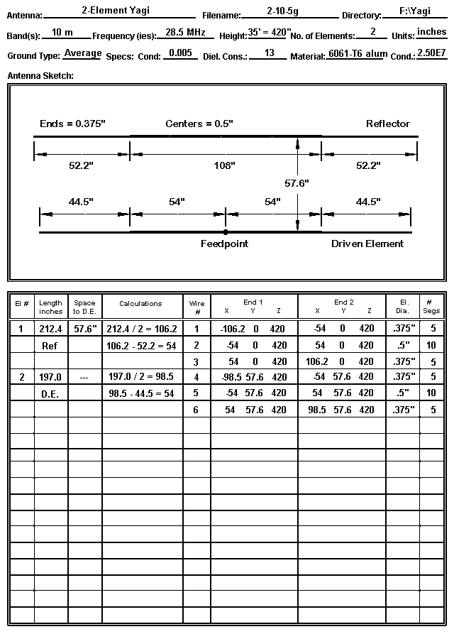
This example is not much more complex than the dipole. However, the differences between the two are interesting. The Yagi design uses inches as the unit of measure and a different type of aluminum from that used for the dipole. Moreover, the antenna is to be modeled over real ground rather than in free space. Both the sketch and the wire table reflect the choice of inches and a ground--the latter evident by the use of a Z-axis value other than zero. (Some programs, such as NEC4WIN, allow you to enter the actual antenna height independently of the Z-axis value.)
In the wire table, element length values appear in the X-axis column. The element spacing is 57.6" but the reflector is set at the Y-axis value of zero, with the driven element set forward of it. This is one of the two most common conventions for single-driver Yagis. The other convention is to set the driven element at zero, with reflectors given a negative value in the spacing column and directors given positive values in that column. Either convention will work, but once more, it pays to select one convention for all (or at least most) of one's work.
Finally, the model is set up for MININEC use, since the driver center wire has an even number of segments and runs symmetrically on either side of the feedpoint at its center.
If racing through the sample models leaves the impression that there are
many things to keep track of in correctly setting up even simple models,
then the importance of preliminary paperwork should be evident. A good
paper model reduces the number of errors and makes the ones that do occur
easier to find. The paper model is fully half the trip from antenna idea
to useful output data.