One of the most popular amateur radio antennas is the tri-band Yagi. It also happens to be one of the hardest antennas to model adequately, whether one is using NEC or MININEC. As a result, there are few, if any, reliable models available to the amateur modeler. The models that do exist tend to be done in one of the implementations of MININEC, unless they use a log-cell driver system. However, most of these models are proprietary. Moreover, many of them are used to guide final antenna design, but they do not represent exact models of the final design.
It may be useful to understand some of the limitations of trying to model tri-band Yagis. The account--which is very general and not tied to the specific circumstances surrounding any particular commercial antenna--may give some insight into why tri-bander models are hard to come by. In addition, it may give the owner of one of these antennas some cautionary notes lest he or she give undue trust to a hasty home-generated model of the station beam. Modeling tri-band Yagis requires the greatest of care.

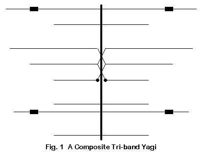
Fig. 1 presents a sketch of a hypothetical tri-band Yagi. Its sole purpose is to register some of the features we shall look at in more detail. First, notice that the elements come in different lengths, each consisting of several different diameters of aluminum tubing. Second, notice that this tri-bander has traps, which are not universal in such antennas. Wherever they do occur, they present modeling problems of several sorts. Third, notice that some of the elements having different lengths are closely spaced. Finally, notice that this particular beam uses a driver system called the log-cell driver.
Each of these features presents either NEC or MININEC with some problems. Not all of the problems are insurmountable, but some may require the use of substitute models, while others simply demand that there be a slight difference between the modeled structure and the physical structure. Still others may leave a few unanswered questions about the precision of the model relative to the real antenna.
1. Tapered-Diameter Elements
Most tri-band Yagis use tapered diameter elements composed of successive sections of aluminum tubing having a decreasing diameter from center to end. These element types present no special problem to MININEC. With NEC-2, the results of directly modeling such an element will be quite erroneous. NEC-4 makes an improvement upon NEC-2 for directly modeling tapered diameter elements, but tends to fall short of some requirements for precision. It grows increasingly inaccurate when the diameter step grows larger. This last condition is often encountered when modelers simulate boom-to-element mounting plates with large diameter, short-length segments.
For a mono-band beam, these limitations can be overcome by careful segmentation of the wires making up an element and through the use of correction factors built into some of the commercial implementations of NEC-2. Variant correction schemes have been developed by Brian Beezley and by David Leeson. These schemes substitute a uniform diameter element of the correct length to give the same electrical performance as the tapered diameter element, thus eliminating the situation that creates errors in NEC-2 outputs.

In a tri-band beam, we introduce a new problem: tapered diameter elements of different lengths, as shown in Fig. 2. MININEC would take this change in stride, since it requires no correction factor for tapered diameter elements. However, NEC-2--even with corrected elements--has a problem. The equations for a corrected element are only accurate within a reasonable margin from 1/2 wavelength resonance--about +/-15%. Commercial implementations of NEC-2 ordinarily provide corrected elements only if the element passes this length vs. frequency test. Elements cut for frequencies other than the band in question will ordinarily not undergo correction for their tapered diameter.
How much error may be introduced into the model by virtue of having uncorrected tapered diameter elements may vary from model to model. My own modeling suggests that 10-meter elements play little role in the 20-meter performance of a tri-bander and have low current levels. Varying their length has in most cases (but not in all cases) little or no effect on any significant 20-meter parameter. Hence, there is little error from having uncorrected 10-meter elements in the model.
The opposite case--the influence of 20-meter elements on 10-meter operation--is quite different. Although the level of influence varies from element to element in various designs, 20-meter directors often carry considerable current on 10-meters and may play a large role in 10-meter performance. In some designs, changes in the length of a 20-meter director can alter the gain vs. frequency curve for 10-meters. Thus, an uncorrected 20-meter element may become an error source when a tri-bander is modeled on 10 meters.
2. Traps
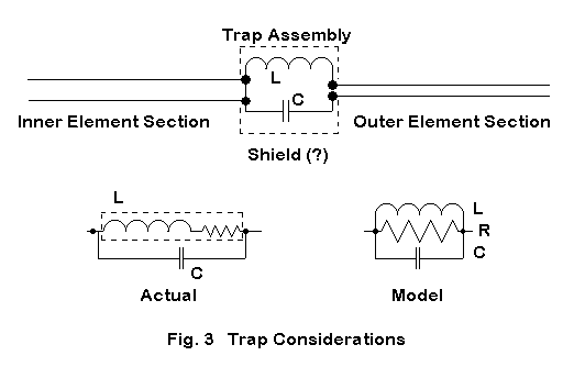
Some tri-band Yagi designs make use of trapped elements. Although many tri-bander designs have eliminated traps from the driven element, they remain in some reflectors and directors. Fig. 3 introduces us to some aspects of the difficulties of modeling trapped elements in Yagi designs.

The upper sketch shows a typical trap in schematic form as inserted into an element. Normally, the trap is configured in the model as a parallel R-L-C "load," which both NEC and MININEC allow.
In NEC-2, the only permissible loads for symmetrical elements are those positioned at the center of the element. The implementation of the tapered diameter correction requires that the curve of current magnitude along the element be continuous, and a load that is not at the center of the element creates a current magnitude discontinuity. Hence, most implementations test for loads outside the center-most segment, and the existence of such a load will defeat use of the correction.
Although the placement of traps along an element is not a concern with MININEC, it is a potential source of error with NEC-2 models. The element remains uncorrected at any test frequency.
The trap itself may call for careful treatment, since the parallel R-L-C mathematical model of the load, shown on the right in the lower sketch in Fig. 3, is a substitute for the circuit shown at the left. For most purposes, the resistance that limits the Q of the trap circuit can be viewed as a series resistance with the inductance (or inductive reactance) of the coil. Setting a value for the resistance in the modeled trap load requires a conversion of the series inductive arm into its parallel equivalent.
Such conversions are straightforward calculations when a parallel resonant circuit is operated at its resonant frequency. However, traps are rarely operated in a truly resonant model. A trap tends to be resonant at a frequency just below the band edge for which it is a trap, giving a net capacitive reactance to the parallel circuit. At lower frequencies, the reactance is inductive, but not simply the inductance of the coil. There are standard handbook equations for calculating the reactance of any parallel tuned circuit off resonance.
The net effect of the change of reactance off the resonant frequency of the trap is to alter the required value of the parallel resistance in the modeled trap with every change in frequency of test. Utility programs exist to ease the calculation of these values (for example, in the HAMCALC suite of utility programs). This requirement is in no way fatal to any tri-bander model (where traps are used in the design), but it does require care on the modeler's part lest the trapped element show greater or lesser losses than exist on the physical element itself.
Series and parallel modeled loads using the LD facilities of either NEC or MININEC are mathematical models, and as such, they do not perfectly model the physical elements they represent. Inductors do not show perfectly equal currents along their length when physically modeled, suggesting that they perform radiating as well as loading functions. The radiating function becomes more pronounced as a coil is moved further from the element's center. When coils are small enough in length and in diameter, the radiating function may approach negligible proportions, but is never zero.
In Fig. 3, there is a "Shield (?)" notation. A trap (or a loading coil) may be placed inside a metal shell, and the shell may be connected to the inner portion of the element, to the outer portion of the element, or to nothing. To this time, I have not seen any reports on the effects of shielding--however connected--on the overall element performance. The presence or absence of a trap shield may or may not constitute a further potential error source for a trapped element.
3. Close-Spaced Elements

Fig. 4 shows a situation that is becoming more common in tri-bander designs: two elements of different lengths in close proximity. These elements may occur in designs which use open-sleeve coupling, where the "slave" 15- and 10-meter drivers are closely spaced to the fed or "master" 20-meter element. The exact spacing and element lengths determine the impedance seen at the feedpoint for each of the bands of operation.
A second situation in which we can find similarly close-spaced elements of different lengths is in the director set. The 20-meter directors may function as part of the 10-meter director set, showing a single current magnitude curve which peaks at the center of the element. However, the 20-meter directors may not be the correct length to provide a 10-meter gain curve where the designer desires it. Placing a 10-meter director of the correct length on the driver side of the 20-meter element can permit the designer to better control the 10-meter performance curves. This new element may be as close as 4-8 inches from the old 20-meter element.
Although MININEC has no trouble with this situation, NEC-2 does. Two elements of significantly different lengths that are closely spaced can introduce errors into the NEC-2 output reports. The effect is subject to a considerable number of variables, including frequency, diameter of the elements, elements lengths, and spacing. The close the spacing, the greater the effect on the model. The full particulars of this limitation, which affects both NEC-2 and NEC-4, were given in "NEC-4.1: Limitations of Importance to Hams," QEX (May/June, 1998), pp. 3-16.
Whether or not a given spacing poses a possible problem can be determined by the gain averaging test. Although the test results have been available in NEC, the test is just now appearing in new versions of commercial implementations of NEC. New versions of EZNEC (for Windows) and NEC-Win Plus will appear later this year or early in Y2K, and both will make the test available. One may test an entire complex antenna. However, where a specific question arises--as in the case of a pair of elements like the ones we have described--we may perform the test on just the element pair by placing a source at the center of the longer element.
For the present case, the test would be performed in free space, with the resistive component of any loads disabled, including the resistivity of the antenna materials. For any antenna in these conditions, the average gain--or ratio of radiated power to power provided--will be 1, taking into account radiation in all possible directions. Ordinarily a fair sampling of directions, as indicated by taking gain readings every so many degrees over the sphere implicit in free space models, will provide a clear indication of how close the average gain of the model comes to 1. Values that deviate too far from 1 make the reliability of the model suspect. (Note: there is no absolute level at which a given model becomes untrustworthy. For some purposes, values above 0.8 and below 1.2 may indicate a usable model, while other modeling tasks may require values within about 0.05 of the ideal 1.0.)
The gain averaging test is a necessary but not a sufficient condition of model adequacy. For example, the gain averaging test may not indicate all of the possible error sources we have described for tri-band Yagis.
4. Log-Cell Drivers
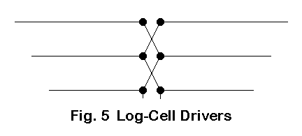
A typical log-cell driver set is roughly shown in Fig. 5.

The log-cell consists of a driver set for the tri-band Yagi so that the set has a single point of connection with the antenna feedline. A true log-cell driver set has crossing lines of connection among the elements. Another driver-set type may use uncrossed connections and has been loosely dubbed "closed-sleeve" coupling. In this latter case, both direct connections and open-sleeve coupling (which depends on element spacing and length for a given source impedance on each band) may be at work.
Modeling both log-cells and closed-sleeve drivers requires the construction of transmission lines from the source to each driver in the set. NEC-2 has fewer problems in creating such a model, since the transmission line is at the element center where currents are balanced. Since the TL facility of NEC-2 is purely mathematical, connection reversal presents no model construction difficulties over and above those of a closed-sleeve driver set. Indeed, the only difficulty for NEC lies in possible accuracy problems that might arise if the elements of different length are spaced too closely, as described earlier.
Modeling the element-connecting transmission line in NEC-2 as a physical set of wires may be more difficult. The connecting wires are normally of a smaller diameter than the elements. Among its limitations, NEC has difficulties with junctions of wires having dissimilar diamters. (This limitation is also detailed in the QEX article referenced earlier.) Consequently, for most purposes (including the modeing of full LPDA antennas), use of the TL facility is recommended. (However, the technique described below as a work-around for MININEC can also be applied to NEC models.)
These same driver sets can also create problems for MININEC, which has no TL facility. Therefore, one can only physically model transmission lines as wires. The log-cell is particular difficult, since the wires must maintain a constant distance between them to effect a transmission line.
Apart from the line spacing, MININEC suffers another difficulty: at sharp angles, the core will "clip" corners and shorten elements unless the segment lengths at the angular junction are very short. Length-tapering routines are provided in some implementations of MININEC to provide short elements at the junction but segments of increasing length away from the junction. These routines are designed to use the least number of segments that can adequately model the element and still hold the total model within the 256 segment limit of the core. (NEC4WIN is the only MININEC 3.13 program of which I am aware that has broken this limitation.)
The log-cell and the closed-sleeve driver sets have a considerable number of right-angle junctions, and the potential for overrunning model size limitations is very good. The development of a MININEC model that can handle such driver-set complexities requires considerable ingenuity.

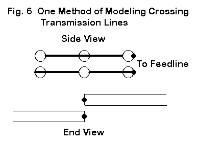
When physically modeling crossing transmission lines, you can avoid extra line bends by using the set-up shown in Fig. 6. Set up two transmission lines as 4 wires (for a 3-driver set). The wires maintain a constant distance from each other, as determined by transmission line construction calculations (available in HAMCALC). Each element is offset from the centerline to intersect the correct wire junction of the transmission line. Alternate offsets as you move from one element to the next. The displacement of the element wires is less likely to create significant modeling errors than trying to maintain a constant distance between undulating wires of a transmission line that tries to bend its way to the connections.
This is only one sample of the variety of modeling techniques that may be required to overcome complexities of design when they run up against limitations of the modeling software.
Conclusion
These notes are titled "Why Tri-Banders Are Hard to Model," not "Why Tri-Banders Are Impossible to Model." Certainly there are models that are sufficient guides to construction and that permit commercial designers to make final prototype adjustments in field tests. Whether these models suffice to confirm performance claims is an issue beyond the scope of these notes. However, to the extent that models require the use of substitute elements or leave open questions about the adequacy of the model to the physical antenna, they may be accounted by some to be less than fully acceptable. Nonetheless, these models will have served a very useful purpose in guiding the development of an antenna. The exactitude we demand of a model is a function of a well-defined set of task goals. (On the other hand, a sloppily defined task does not justify acceptance of a sloppy model or its over-optimistic performance predictions.)
In terms of modeling one's own tri-bander, these notes may serve as a reminder of the caution one must use in building the model. There are limiting boundaries for both MININEC and NEC that one may cross without noticing them. Use great care in trying to model a tri-band Yagi--the job is harder than you may initially think.