The final question in our inquiry is whether Type 0, 1, or 4 mathematical loads (each within their application limitations) fully or adequately specify inductively reactive loads used in a shortened antenna. Answering this question via antenna construction would seem natural, were it not for our customary building practices and presumptions. When we install a loading coil and it proves too large relative to the wire length, we simply shorten the wire to match the coil. Then we fail to interrogate the situation further to discover why the coil was too large. Most of the time, we assume that we miscalculated or that the usual coil equations are not sufficiently accurate to yield a coil that requires no subsequent wire pruning.
As a consequence, few modelers have explored the behavior of helically wound single layer solenoid inductors in their models--simply because winding a coil is too laborious a task relative to using the loading facilities built into NEC. We have presumed that the loads--especially Type 0 series R-L-C loads--adequate specify the loads we need.
Yet nagging suspicions remain about such loads. The current differential that is present at each end of the load suggests that--like their linear load counterparts--these loads do not act like pure inductances, but may also function as simple current bearing wires. Models of helical dipole elements show very usable gain, which parallels the experience of those who have constructed such antennas. I guess we shall not know whether mathematical models of loads accurately reflect the operation of single layer solenoid inductances unless we actually wind some model coils and replace the Type 0 loads with them.
The basic model for the half-size (1/4 wl) 7.15 MHz dipole uses #8 (0.125" diameter) zero-loss wire that is 412.68" (34.39') long and divided into 91 segments. Each segment is about 4.53" long. For least error, the segments within the helix will be as close to this value as helix construction permits.
The required center loading reactance for the antenna is 833.3 Ohms or 18.549 microH. We may let the coil be 3 segments long or 13.6" overall. Using the standard Wheeler equations (either the common 1928 version or the 1982 version), a circular single layer solenoid inductor of this length will require 10 turns and an 11.852" diameter.
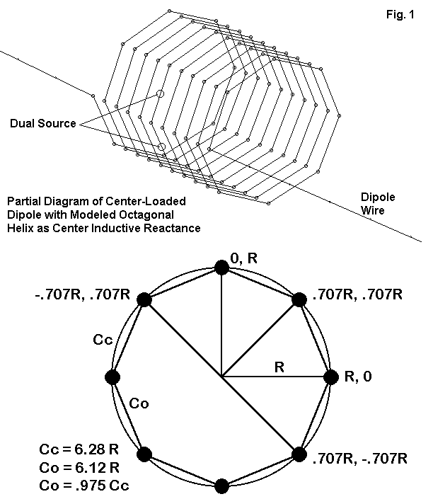
The most reasonable approximation of a circular solenoid is an octagonal structure. Fig. 1 shows the resultant structure and the basic relationships that determine the coordinates of the points around each loop. For this exercise, let's adopt the convention of extending the turns along the X-axis and using the Y-axis and the Z-axis for the radial points of each loop. Under this convention, the point references in the lower part of the drawing refer to Y and Z coordinates. Beginning, perhaps, with half the diameter as the value of R (5.926"), we might place the first entry at 0, 5.296, 0 (assuming a free space modeling environment). Intermediate points between the horizontal and the vertical will require values of 0.707 R (3.744"). (Note: rounding to one less decimal place will make no significant difference in the long run.)
Each point progresses along the X-axis by the total length (13.6") divided by the number of turns (10) divided by the number of points in each turn (8), for a value of 0.17" in this case. Hence, the second point of the turn will be located at 0.17, 3.744, 3.744. We can then proceed to complete the first turn. Then, using whatever copy function may be present, we add progressively more turns, increasing the value for the X- coordinate by 1.36 with each turn.
The resulting solenoid will be about 2.5% short in overall wire length used compared to a truly circular solenoid, suggesting a slightly lower inductance than provided by the Wheeler calculation. Since the wire is small compared to the turns spacing, a slight additional variance may also be encountered. Of greater significance for the model, each wire in the helix is about 4.56" long, a close match to the length of the segments in the remaining portions of the dipole wires.
Once the coil is complete, it should be saved as a file, since we may use it later. For the initial test of center-loaded short dipole, we may replace the center 3 segments of the basic wire with the helix. The best coordinates for the coil may be -6.8 to + 6.8 on the X-axis to obtain a useful symmetry in the now enlarged geometry sheet--useful for visual error trapping. The formerly single wire is now two wires extending to + and to - 206.343" respectively, and each with 44 segments.
Part of the extended exercise in looking at NEC loads, both mathematical and physical, has involved sorting out the losses attributable to the load from those which may be associated with the linear wire portion of the antenna. For this purpose, we shall need to make the linear wire lossless and the coil wire of a suitable material, namely, copper. At present, only GNEC (Nittany-Scientific) permits a wire-by-wire material selection. Fig. 2 shows a partial .NEC file from GNEC, with the dimensions in meters.

The portion of the model shown shows the last few turns of the helix, wire by wire. The last wire (82) is the linear dipole wire in the +X direction. Skipping down to the Type 5 load lines (material loading), we see that wire 1 (and also 82) is skipped, being lossless, while the conductivity value for copper appears for each wire in the helix.
Finally, because the turns of the helix have an equal number of wires per turn, a split feed is used at the wires forming the very center of the inductor.
The model just constructed in a free space environment yielded an inductive reactance of over 86 Ohms, indicating not that our octagonal coil was slightly small, but rather that it was considerably too large. Achieving resonance required a significantly smaller helix. In order to preserve the length of the coil that was equal to 3 segments of the linear wire, the coil was reduced in diameter. With a diameter of 11.12" the loaded antenna achieved resonance (as defined in this study as less than +/- 1 Ohm source reactance). Wheeler calculations for a circular coil of this diameter, length, and number of turns yielded an inductance value of about 16.6 microH, roughly 10% less than the value called for by the mathematical load systems provided in NEC. The length of the coil wires reduces to about 4.25" each, which is unlikely to induce any significant error in the model.
The following table provides some basis for making comparisons between the physically modeled load and the Type 0 loads used in earlier parts of this exercise. In all cases, the linear portion of the antenna is composed of lossless wire.
Load                Free Space          Source Impedance
                    Gain dBi            R +/- jX Ohms
Lossless Type 0     1.85                13.19 - j 0.02
Q=300 Type 0        1.02                15.97 - j 0.01
Copper Helix        1.35                10.61 + j 0.64
The higher gain provided by the physically modeled center load should not be surprising, considering that the helix contains wire that radiates. See Fig. 3.
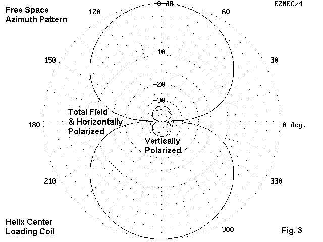
The small but definite vertically polarized radiation field results from radiation from the portions of the helix that are vertically oriented. This field alone would not suffice to provide the added gain over the Q=300 center loaded model, but the entire 13.6" length of the inductor would. More precisely, that portion of the overall inductor wire beyond the 13.6" it replaces in the overall antenna length would suffice to provide additional gain.
The actual Q of the inductor cannot be ascertained with accuracy. Some calculations estimate the Q at over 400, but only under the conditions that the wires be closer to half the spacing between turns. The modeled helix uses much smaller diameter wire, resulting in a decrease in Q, perhaps to the 200-300 range at best.
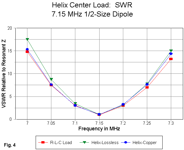
Despite the lower Q estimate, the source impedance of the physically modeled helical loaded dipole is lower than even the Type 0 model at zero load loss. As Fig. 4 shows, the SWR curve is slightly steeper than even the R-L-C lossless load model--and a lossless helix yields a steeper curve yet.
The actions of the physically modeled helix load are in part a function of the current magnitude and phase profile along the coil. Fig. 5 shows the two curves from the center point outward toward the end.
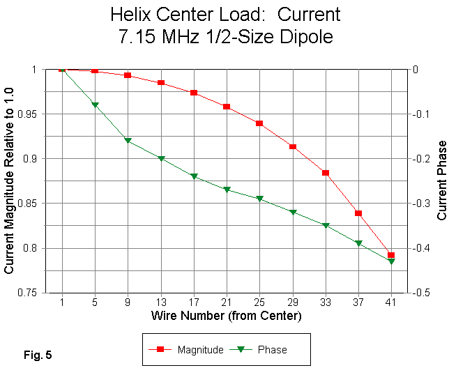
The current magnitude differential between the source and the coil end is approximately 20% of the maximum value. Since the inductance of a helix is in theory predicated upon equal current magnitudes at both ends of the coil, the differential currents dictate that in part the indictor does not act solely as an inductor. The physical model of the center load provides indications that the helix also radiates in the manner of any length of wire included within the total length of the dipole--in terms of gain over the Type 0 load, the vertical radiation field, and the reduction in the required inductance to effect loading to resonance.
There are potential error sources within the model. First, the octagonal inductor with less then optimal wire diameter relative to turns-spacing casts some doubt on the precision of the calculations relating inductance to turns, diameter, and length. However, most of these factors suggest that the octagonal coil's inductance would be low, when in fact, the model showed it to be very much higher than required for resonance.
Second, the helix design, although apt to the modeling task, is very large and open compared to coils one might ordinarily apply as center loads in a shortened dipole. However, as an error source, the helix configuration would be a matter of degree and not of fundamental principle of operation. What the dimensionless load of a Type 0 load does not show is the relatively large early drop of current magnitude along the total length of the dipole. Fig. 5 shows the more dramatic drop occasioned by the physically modeled coil. Although different coil configurations may alter the amount of drop somewhat, the current magnitude curve is unlikely to resemble that for the Type 0 load.
The plausibility of the physical model might be put to still another test. The original short dipole model was designed to permit one to place load values equal to the center load value at specific mid-element points. If the center load helix as modified to achieve resonance acts like a Type 0 load, then placing the same coils at the specified points should also result in resonance.
The original model was modified into a 5-wire model having the same operational characteristics as the original. The inserted 3-segment wires were placed at points between 99.5" and 113.1" from the center so that the Type 0 load was positioned 106.3" from the center. At these positions either side of center, a load of 833.3 Ohms (18.549 microH) resonated the antenna. The value of these two loads was the same as the value of the single center loading reactance.
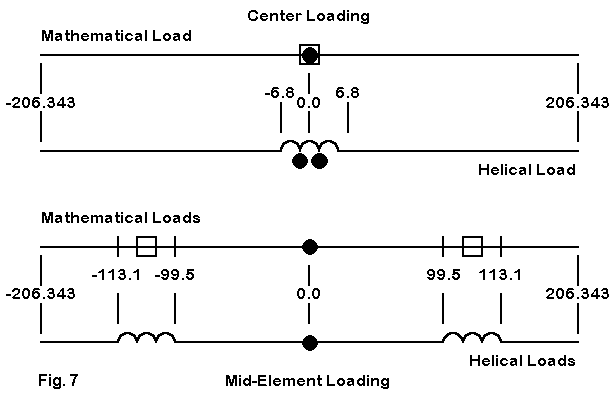
As shown in Fig. 7, the helix developed for the center load may directly replace the inserted 3-segment wires in the 5-wire model. By copying the original helix and changing the values for all of the X coordinates by the same amount, each coil may be placed in the correct position. The connection points to the coils are very slightly displaced relative to the axis line, but not by an amount to show up in a movement of the antennas resonant frequency. The 11.12" diameter (R = 5.56") helix was copied and transferred to these points and the model run.
The result was a source impedance of about 29 + j 229 Ohms, indicating that the inductor size (16.6 microH) was much too large for resonance. This result was consistent with but considerably larger than expected. To create helices that allowed the overall antenna to achieve resonance required a reduction in the coil diameter to 10.2" (R = 5.10"). By Wheeler calculations, the inductance was reduced to about 14.3 microH for a truly circular coil. The wire length from coil point to coil point diminished to 3.90" compared to linear wire segment lengths of 4.53" each.
The amount of reduction in coil size was about 14% relative to the final center loading coil and almost 23% relative to the inductance required by a Type 0 load. This reduction is consistent with several factors involved in inductive loading, including the fact that the further out along an element one places the inductor, the less it acts as an inductor and the more it acts as a compact form of wire length to increase the overall wire length to resonance. By the outer ends of a shortened dipole, helices and others forms of element extension cannot be viewed as inductances almost at all.
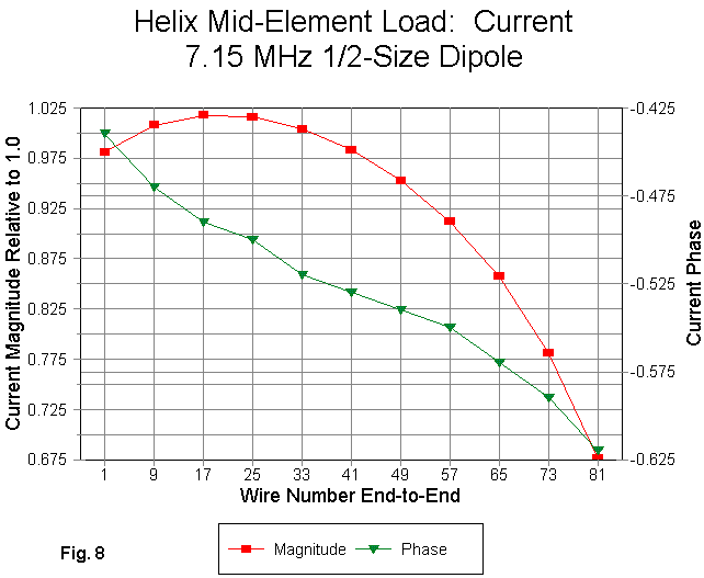
The current magnitude and phase profile within the helix may be of some surprise to some. Along the mid-element loading helix, after size adjustment to resonance, the current does not show a steady progression lower in magnitude. Instead, there is a current peak about a fourth of the way outward from the inboard end of the coil. From that point onward, the current magnitude descends rapidly. The phase transition, although not linear, generally follows the progression along the entire antenna element.
Compared to the center loading coil, the current magnitude excursion within the inductor is about 34% of the maximum value, and the end to end difference is about 30% of maximum current magnitude. This compares to the 20% differential from center to end for the center loading coil. The greater differential of current magnitude along the mid-element inductor wire is another indicator that it is functioning to a greater extent than the center loading coil as part of the element length and hence requires less inductance and inductive reactance to effect loading to resonance.
Like the physically modeled center load, the physically modeled mid-element load shows a much larger drop in current at its outer end than does a corresponding Type 0 load. The dramatic decrease in current immediately outside the loading helix appears vividly in Fig. 9, with the Type 0 load curve shown for comparison.
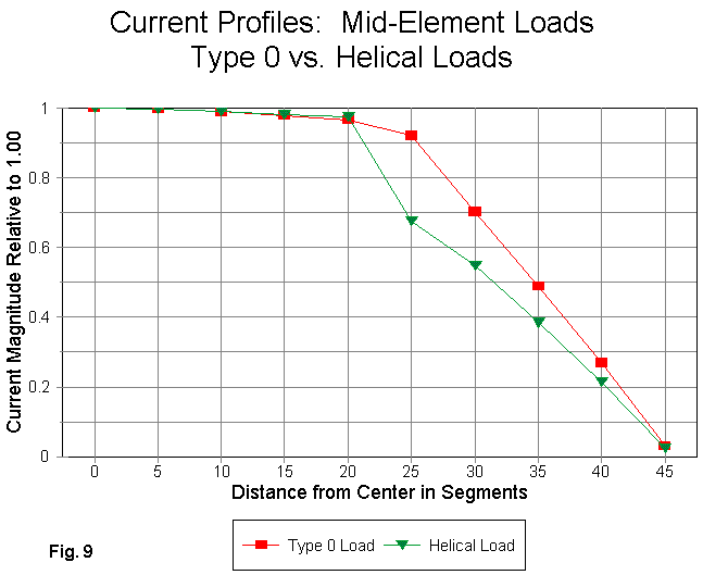
Despite the close correspondence of current up to the load position and the dramatically lower current beyond that point for the physically modeled helix, the model shows a significantly higher gain than either the corresponding Type 0 load model or even the physically modeled center load. The following table summarizes the gain situation for various models.
Antenna                            Free Space          Gain Relative to a
                                   Gain dBi            Full Length Dipole
Full-Length                          2.14                   ---
Half-Length Lossless Wire            1.85                   -0.29 dB
Type 0 Center Load, Q=300            1.02                   -1.12 dB
Helical Center Load, Copper          1.35                   -0.79 dB
Type 0 Mid-Element loads, Q=300      1.11                   -1.03 dB
Helical mid-Element Loads, copper    1.71                   -0.43 dB
The gain figures strongly suggest that the current within the turns of the helix is not going wholly to waste within a tightly coupled inductive field. That part of the current not devoted to the field, as indicated by the current differential at the coil ends and among the turns is contributing to the total field of the antenna.
The use of Type 0 loads to characterize both center and mid-element loading strongly suggests that there is little difference between the gain potential of two antennas of equal length loaded in each manner. However, physically modeled loading helices tell a quite different story. Not only do both types of loaded antennas potentially perform better than mathematically inserted loads would indicate, but as well the empirical experience giving the nod in gain to mid-element loading gains some support from the physically modeled loading coils.
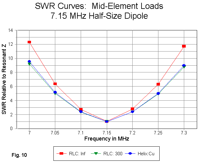
Although the physically modeled center loaded antenna showed a steeper SWR curve than its Type 0 counterpart, the mid-element loaded antennas show a good correspondence between mathematical and physical loads. In fact, as shown in Fig. 10, the mid-element physical helices correspond nicely to mathematical loads with a Q of 300. This curve corresponds reasonable well with estimates for the Q of the coil at or just below 300, based upon reductions from the calculated Q of over 400 that presumed an ideal wire diameter to spacing ratio. The resonant source impedance of about 24.6 Ohms is a bit lower than the Type 0 model at Q=300, where the source impedance was about 31.9 Ohms.
It should be noted for accuracy and completeness that the actual resonant frequency for the model using physically modeled mid-element coils with a 10.2" diameter was 7.16 MHz, and that the curves for this antenna actually run from 7.01 to 7.31 MHz. This 10 kHz displacement did not seem great enough to warrant reconstruction of the coils through the iterations necessary to move the resonant frequency. The estimated diameter would have been something of the order of 10.205" +/- 0.002" for resonance at 7.15".
The potential error sources for the mid-element load model remain the same as for the center loading coil. The octagonal helices may in fact show a lower inductance than the values calculated by the Wheeler equations. Moreover, the widely spaced open helix may prove a better radiator than some more tightly wound loading coils. Unique to the modified mid-element loading coils is the shortening of the wires and a somewhat greater differential to the lengths of the segments in the linear wire portions of the antenna.
Some of these possible error sources work in the wrong direction relative to the results, for example, the reduced inductance of octagonal helices relative to truly circular ones. The sum of the remaining error sources appears to be far short of what would be required to account for the radical reduction in required inductance for the loading coils. Indeed, the most telling part of the demonstration is the further reduction in coil size required in moving the center-loading inductor out to the position where the same value should have served as a mid-element loading inductor. Although absolute values of the inductors involved may be off the mark by some small amount, the trends are in all probability accurate reflections of anticipated antenna performance.
As a consequence of these data and considerations, the bottom line seems inevitable: Type 0 (and by extension, Type 1 and Type 4) loads do not fully characterize the performance of inductively reactive loads in the form of single layer solenoids. For many purposes, that characterization may be adequate to a design task. For example, where design criteria permit adjustment of the antenna outer section length, designing to the Type 0 load value may cause not harm.
However, using mathematical loads alone can give a potentially misleading impression of the gain of the loaded antenna. The gain for physically modeled loads is considerably higher than the gain for mathematical loads. Where multi-element arrays--such as Yagis--may employ center or mid-element loads in all elements, Type 0 load models may seriously underestimate the overall array gain.
This exercise, along with the previous portions of this study, should be viewed as only a beginning to the investigations into modeling loaded shortened antennas. Further work might yield additional insights into the behavior of linear loads examined in the last episode. Likewise, for helical inductive loads, much remains to be done with respect to the use of more compact forms of inductance. Even using these models, additional data can be gathered for the use of linear wires with non-zero losses and for the use of other helix materials, such as aluminum.
Nonetheless, if the present demonstration holds up as reasonably valid, then the suspicion raised at the outset has been established. In several important respects, the mathematical loading features provided within NEC do not fully characterize the action of these loads when physically modeled. Nevertheless, modeling actual loading inductors that form junctions with elements of radically different diameter from the coil wire and modeling small-diameter coils without violating adjacent segment length restrictions may prove to set major challenges for the amateur and the professional modeler. This study was carefully designed to use models that stayed well within all NEC restrictions. Most real antennas that use inductive reactance to electrically lengthen a physically short element will press those restrictions or result in quite large models.
In other words, what we can establish in principle in a straightforward manner might prove to be an exceptional modeling challenge when real antennas and their parts are involved. Loads are not quite as simple as casual modeling might lead us to believe.