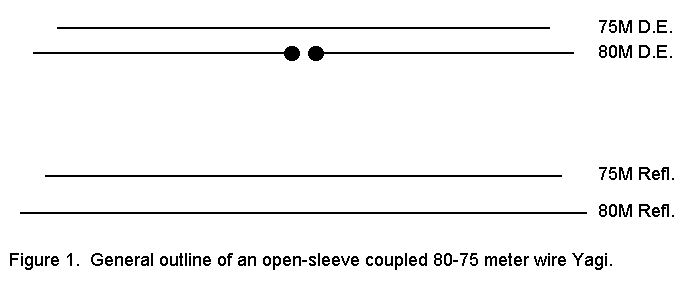

Hanging a wire beam for 80 or 75 meters is difficult enough without having also to support complex matching networks. Separate beams appear to call for separate antennas and feedlines--again, a double weight. Enter open sleeve coupling. It is possible to construct beams for 80 and 75 and to position them so that feeding only the 80 meter driven element will provide adequate performance at both ends of the band.
The general outlines of such a 2-element wire beam appear in Figure 1. The higher frequency driven element--the one not connected to the feedline--is ahead of the driven 80-meter element, with the corresponding reflectors appropriately aligned.

To see what such a beam might look like in practice, I modeled a couple of versions using slightly different driven element spacings and slightly different basic driven-element-to-reflector spacings. In common, both version use #12 copper wire and both beams are 136' above ground, approximately 1/2 wavelength. At that height, the angle of maximum radiation is approximately 27 degrees, assuming as NEC does, level terrain.
As a suggestive beginning for refinement by builders, here are the dimensions of each version and the NEC-derived anticipated performance from one end of the band to the other.
Version 1:  Driven element spacing 3'; overall front-to-back distance 42'9"

Dimensions:

75 DE (no connex)  122'5" long  space =   0
80 DE (coax conx)  134'0"               - 3'
75 REF             128'4"               -36'8"
80 REF             139'0"               -42'9"

Predicted performance:
FQ       Gain dBi    F-B dB     Feed Z ohms    SWR @ 75 ohm line
3.5      11.4        11.5        47 - j 18      1.7
3.55     11.0        13.0        76 - j  5      1.1
3.6      10.3         8.0        88 - j  9      1.2
3.65      9.2         3.7        79 - j 11      1.2
3.7       8.7         2.5        52 + j  7      1.5  Reverse direction
3.75      9.5         1.1        45 + j 81      4.0  Reverse direction
3.8      11.6        11.7       158 + j 73      2.7
3.85     11.2        11.6       107 + j  3      1.4
3.9      10.8         9.8        51 + j 24      1.7
3.95     10.1         9.1        21 - j 64      6.3
4.0       8.2         9.7         8 + j106     28.0
Version 2:  Driven element spacing 3'6"; overall front-to-back distance
39'6"

Dimensions:

75 DE (no connex)  121'8" long  space =   0
80 DE (coax conx)  133'0"               - 3'6"
75 REF             127'5"               -33'2"
80 REF             138'0"               -39'6"

Predicted performance:
FQ       Gain dBi    F-B dB     Feed Z ohms    SWR @ 75 ohm line
3.5      11.2         6.8        28 - j 37      3.4
3.55     11.3        14.0        55 - j  7      1.4
3.6      11.7        10.3        82 - j  2      1.1
3.65      9.9         5.9        86 - j 10      1.2
3.7       8.4         1.6        68 - j  8      1.2
3.75      9.9         7.3        37 + j 25      2.3  Reverse direction
3.8      10.9         4.9        70 + j114      4.2
3.85     11.4        12.4       147 + j 34      2.1
3.9      10.9        10.6        72 + j 11      1.2
3.95     10.3         9.5        29 + j 49      3.9
4.0       9.0         9.7        11 + j 93     17.6
The two versions are peaked at slightly different points on the band, but there is little to choose between them. Indeed, with appropriate tweaking of reflector lengths and spacings, performance improvements can be garnered. However, improvements are more likely to be those suited to an individual's desired "main" frequency rather than to overall performance across the band.
The phrase "Reverse direction" refers to the forward lobe of the beam being in the reverse direction or toward the reflectors for the frequencies indicated. The 80-75 meter ham band is sufficiently wide, relative to the frequencies involved, that with a wire antenna, 3 beams would be required for full band coverage without reversal or excessive SWR somewhere along the way.
One limitation of these antennas relative to reality is that they were modeled flat, without the usual droop of wire. However, the absence of major differences between the two versions, despite the changes in driven element spacing and the D.E-to-reflector spacing suggest that droop alone will not seriously change performance.
75-ohm coax, with a choke or bead balun, seems the most versatile feed system for these antennas. At 80-75 meters, moderately high SWRs do not incur nearly the level of line losses as they do in the upper HF region; consequently, an ATU should allow matching to rigs with SWRs of 5:1 and under.
These notes are not intended to be definitive, but only suggestive of one
more way to obtain gain and directivity in the 80-75 meter band.
construction details will be dictated by available support structures, and
final design will fit the refinements occasioned by specific operating
goals. The models do suggest very strongly that open-sleeve coupling is
not confined to upper HF beams and lower HF dipoles. A single-feed wire
beam for both the CW and SSB portions of the 80-75 meter amateur band is
both possible and practical.
Updated 4-9-97. © L. B. Cebik, W4RNL. Data may be used for
personal purposes, but may not be reproduced for publication in print or
any other medium without permission of the author.