 17-15-12 and Simple
A number of casual CW operators have expressed interest in the 17-, 15-, and 12-meter bands as favorites for operating. QRM is less, in general, and the "atmosphere" seems relatively friendly. The smaller population on at least the 2 WARC bands in this collection also makes them easier for the less experienced operator to use.
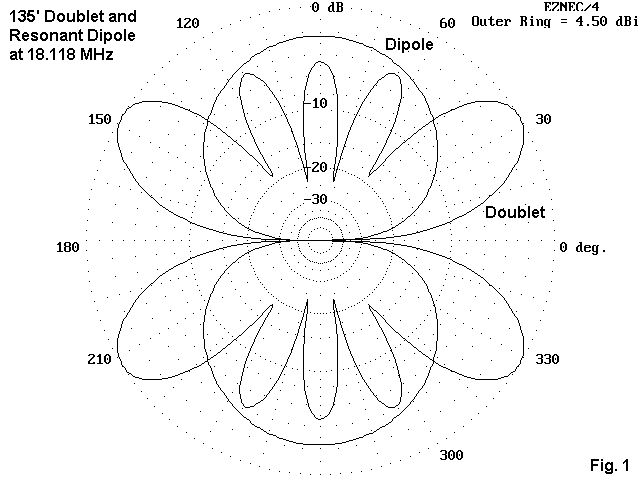
A common thread of conversations about antennas for these bands runs something like this: The lobes of the 135' doublet seem to prevent full coverage of all directions. Even though it has somewhat more gain near the ends, the lobes are narrow with deep nulls between.

As Fig. 1 demonstrates, these problems are correctly diagnosed. Compared to dipole cut for 17 meters, the pattern for the doublet on 17 has many thin fingers. On 15 and 12, there will be more fingers, and thinner.
However, the typical antenna described as being just for these bands is usually a complex beam of interlaced elements. Construction is usually tricky. A commercial version is expensive. So the conversation next poses this question: Is there something simpler, less expensive, and fuller in beamwidth coverage that might be used?
The answer is yes. Unfortunately, the idea of using drooping dipole fans turns out not to be the most desirable option. The closeness of frequency of the 3 bands makes the interaction quite strong, even with sizable angles between wires. Hence, feeding one antenna array with a single coax cable may not be the easiest route to success. It can be done with careful pruning, but there may be an easier way.
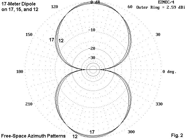
We can use a fixed or a rotatable dipole for 17 meters fed with parallel transmission line to an antenna tuner (the one used with the doublet). By cutting the dipole for 17 meters, the antenna will still be only about 2/3 wl long at 12 meters. Hence, the pattern will not change its shape from the dipole figure-8 (in free space) by enough to matter as we raise the frequency through 21 and stop at 24.99 MHz.

Fig. 2 compares the patterns for a 17-meter dipole in free space in the three desired bands. Operationally, the differences in patterns would not be detectable.
One important feature will change: the feedpoint impedance. If resonated in the middle of 17 meters, the impedance will be about 72 Ohms. On 15 meters, this same antenna will show a feedpoint impedance of about 130 + j200 Ohms. On 12 meters, the impedance will be in the neighborhood of 270 + j500 Ohms. The exact reactance value will vary with the wire size. 50-Ohm SWR values can get as high as 17:1 to 20:1.
The upshot is this: if the antenna is to be used on all three bands, it needs to be fed with parallel transmission line and an antenna tuner. This move also frees us from having to use ultra-precision in adjusting the length of the dipole.
If the antenna is placed at least 1/2 wl up in the air, skip performance will be excellent broadside to the antenna. A half wavelength at 17 meters is only about 27' up, so anything above that level is a bonus in terms of lowering the elevation angle of the main radiation lobes. The beamwidth of the dipole pattern is wide enough to make pointing very non-critical.
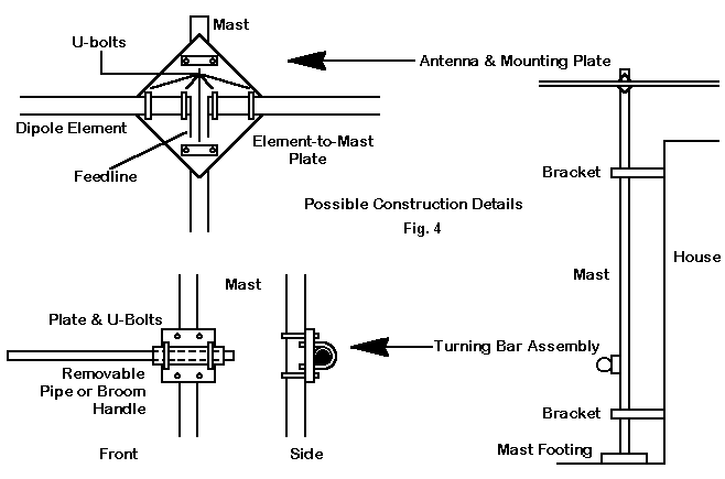
A thirty-foot TV mast might be pressed into duty for this antenna. The metal mast will require some attention to dressing the parallel feedline down to the shack to avoid unbalancing influences, but most handbooks have sage advice in this department. The mast might be set up to turn with a rotator or by hand--what used to be called the Armstrong method. A short piece of strong tubing mounted to the mast with a plate and U-bolts would make room for a removable rod or thinner pipe to ease the turning. The system described here is designed to let you store the turning pipe when not in use for family safety. Other methods both simple and complex can be used.
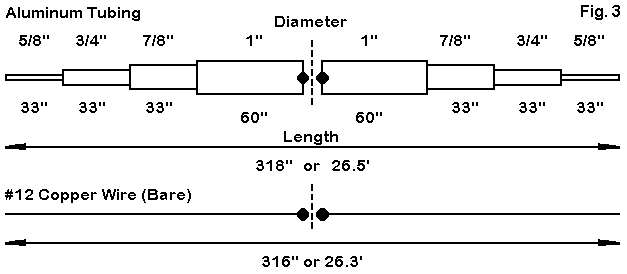
The system just described calls for an antenna that can be supported at the center at the mast top. See Fig. 3.

The sketch shows two ways (among many) to make up the dipole. The tubing sketch makes use of standard aluminum tubing available from places like Texas Towers and others. It comes in 6' lengths and the sizes nest closely in each other. Hence, little work is necessary to lock smaller sections inside larger ones. Handbooks, show hose clamp, bolt, sheet metal screw, and rivet methods of element joining. Pick the one most easily implemented, but do not skimp on the effort to make the junctions secure.
The tubing lengths in the diagram have a plan. The 33" exposed sections are all 36" long, with a 3" insertion length into the next larger tube section. This feature allows the builder to use a single 6" length of each size--and 6' is the standard shipping length. The 1" sections need 2 6' sections, with a bit left over. (A short section of fiberglass rod or tubing at the center of the 1" sections and running at least the length of the plywood plate can keep the elements aligned and strengthen the mounting.) Hence, even with shipping charges, the materials for this rotatable version of the 3-band dipole are inexpensive.
The center plate can be a 1' to 1.5' per edge square of exterior grade plywood (exterior on both sides). Orient the plate as a diamond. Several coats of spar varnish weather protect the plate. It pays to use an exterior grade fill on the plywood edges before varnishing. U-bolts hold the element to the plate (4: 2 for each side) and the plate to the mast (1 U-bolt top and bottom). There are sources, like Harbach, for U-bolt assemblies designed specifically for antenna work. Hardware depot supplies should be carefully checked to ensure they are stainless steel.
Some of the possible construction ideas appear in Fig. 4.

Use any kind of insulated stand-offs to space the parallel transmission line from the mast. Then get plenty of help to raise things into position, thinking safety all the while. A 26.5' antenna can be somewhat ungainly.
The fixed wire version can be used, although getting it to rotate is more difficult. However, bamboo may still be available in some areas. Otherwise, one has to live with a fixed wire, so be sure the antenna is broadside to your favorite parts of the world.
Notice that the thinner wire dipole is actually shorter than the aluminum tapered diameter element. The particular set of element diameters and section lengths used in the tubing model actually is equivalent to a uniform diameter tube about 0.8" in diameter and 310" long. Tapering element diameters downward towards the outer ends calls for longer physical lengths longer than uniform diameter tubes.
The actual length of the wire version will depend on the wire used. Insulated wire usually requires some physical shortening, since insulation gives antenna wire a velocity factor between .95 and .99 depending on the insulating material and its thickness. However, if we use the parallel feedline, length is less critical since we are no longer striving for a perfect impedance match at any frequency of use.
Although designed for 17-12 meters, the antenna can be useful up to 10 meters and down to 30 meters. At these frequencies, the tuner might have some difficulty in reaching a match, but changing the parallel line length slightly may present the tuner with values of reactance it can more easily handle.
A rotatable dipole can be a very effective antenna, since it eliminates QRM off the sides. (A beam reduces QRM on only one more side than the dipole.) Its broad beamwidth makes orientation easy. On many days, it is only necessary to reorient the antenna in late morning and again in late afternoon. (Of course, on other days, skip may come from anywhere, and the run to the antenna for a change of direction can be counted as good exercise.) The simplicity of construction, inexpensive materials, and ease of maintenance go a long way to compensate for lower gain relative to complex, expensive Yagis. Parallel feedline keeps losses low and places the matching problem next to the rig, where it can be handled with ease.
If you already have your towers and beams, by all means use them. But for the casual CW operator who enjoys a rag chew on the upper bands or the pursuit of QRP with less QRM, a rotatable dipole for 17-15-12 meters may be just the ticket to getting started.
Updated 5-18-99. © L. B. Cebik, W4RNL. Data may be used for personal purposes, but may not be reproduced for publication in print or any other medium without permission of the author.