


|
|
 |
 |
 |
|
|

Antentop is FREE e-magazine devoted to Antennas and Amateur Radio an
Special page devoted to
End Fed 6- meter Zepp Antenna with Resonance at 2- meter Band

Custom Search
|
ANTENTOP- 01- 2020 # 024 |
End Fed 6- meter Zepp Antenna with Resonance
at 2- meter Band |
|
|
|
|
|
|
Two
wire line and wire in plastic insulation both has the own velocity
factor (or shortening factor). It means that physical length of
the quarter wave transformer and the half wave antenna should
be less the shown in the Figure 1.
I do not know the velocity factor not for wire neither for two
wire line it should be find in my experiment with the antenna. So
I made antenna according the Figure 1. The antenna was hanged up to the ceiling
of the room in my house. Antenna feed through 50- Ohm coaxial
cable in 3 meter length. I begin tune the antenna to 50.1- MHz
(because I work CW on the 6 meter band) by shortening antenna
wire and quarter- wave transformer. For tuning the antenna I used
MFJ- 259. Figure 2 shows final variant of the antenna with
1.0:1.0 SWR at 50.1- MHz. |
Photo 2 RF- Choke |
|
|
Figure 2 Final Variant of the Antenna with
1.0:1.0 SWR at 50.1- MHz |
||
|
Practical
found velocity factor for the 450-Ohm MFJ Two Wire Line is 0.765
and practical found velocity factor for the electrical green wire
is 0.89. It is quite close to the supposed theoretical value.
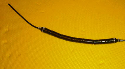
Figure 3 shows real design of the 6- meter Zepp antenna. I
used two porcelain dog bone ribbed insulators at the ends of the
quarter wave line. A porcelain egg insulator was installed at
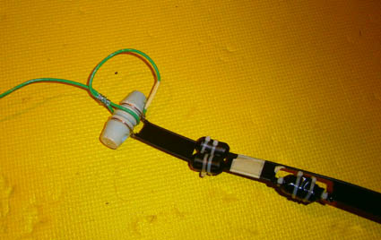
the end of the half-wave antenna. Photo 3 shows the antenna wire connection to the two wire line. Photo 4
shows the coaxial cable connection to the two wire line. This
antenna was again hanged up to ceiling and antenna parameters
were measured with the help of MFJ- 259. The antenna requires
some small tuning. To achieve the resonance at 50.1 MHz and a
resistance of 50 ohms at this frequency, the antenna wire was
shortened by 2 cm, and three small ferrite clips were installed
on the two wire line (see Photo 3). |
Photo 3 Antenna Wire Connection to the Two Wire Line |
|
|
Figure 3 Real Design of the 6- meter Zepp Antenna |
||
|
|
|
|
|
|
Page- 69 |
|
 |
 |
|
 |
|
|
|||
Just for Fun:

Powered byIP2Location.com
Thanks for your time!
Last Updated:
October 4, 2020 21:42