
Antentop is FREE e-magazine devoted to Antennas and Amateur Radio an
Special page devoted to
UR0GT Wideband Antenna for 27- 30- MHz

Custom Search
|
ANTENTOP-
01- 2020, # 024
|
UR0GT Wideband Antenna for 27- 30- MHz |
|||
|
|
||||
|
As well it is not critical
the diameter of the vertical antenna and diameter of the wire
in coupling loop because the variable capacitor dopes the main
match the coaxial cable with the antenna. At the feeding end of
the coaxial cable should be installed several ferrite ring- it
is needs to isolate the coupling loop from the influence of the
coaxial cable. Design of the Wideband Antenna for
27- 30- MHz is shown in Figure 1. There are three variant of the antenna,
A- feeding to the center bottom of the coupling loop, B- feeding
to the center side of the coupling loop and C- feeding to the
corner of the coupling loop. All of the variant may be suitable
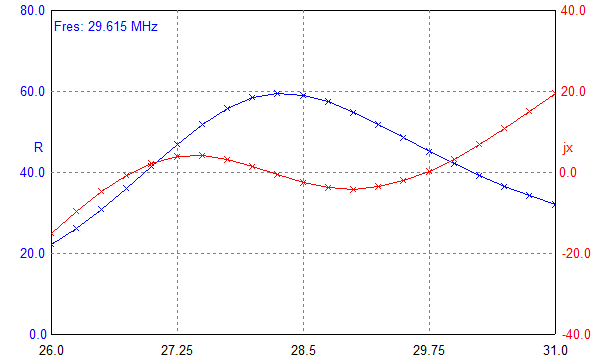
for certain installation of the antenna. Figure 2 shows Z
of the UR0GT Wideband Antenna for
27- 30- MHz with feeding
to the center bottom of the coupling loop.
Figure 3 shows SWR of the UR0GT
Wideband Antenna for
27- 30- MHz with feeding
to the center bottom of the coupling loop. |
Figure 4 shows DD of the UR0GT Wideband
Antenna for 27- 30- MHz with feeding to the center bottom of the coupling loop. Figure
5 shows SWR of the UR0GT
Wideband Antenna for
27- 30- MHz with feeding
to the center side of the coupling loop. Figure
6 shows SWR of the UR0GT
Wideband Antenna for
27- 30- MHz with feeding
to the corner of the coupling loop. DD of all of the three antennas
almost the same. Vertical radiator needs good grounding. It may be several
counterpoises of different length or metal plate under the antenna.
The antenna may be scale for other band, for example for 50- MHz.
73! de
UR0GT |
|||
|
|
||||
|
The MMANA filel of the UR0GT
Wideband Antenna for
27- 30- MHz may be loaded: http: // www.antentop.org/024/UR0GT_wb_27-30_024.htm |
||||
|
|
|
|||
|
Figure 2 Z of UR0GT Wideband
Antenna for 27- 30- MHz with Feeding to the Center Bottom of the Coupling Loop |
||||
|
|
||||
|
Page- 62 |
||||
 |
 |
|
 |
|
|
|||
Just for Fun:

Powered byIP2Location.com
Thanks for your time!
Last Updated:
January 30, 2021 19:53


