
|
|
 |
 |
 |
|
|

Antentop is FREE e-magazine devoted to Antennas and Amateur Radio an
Special page devoted to
Balcony Dipole Antenna for 20, 15 and 10- meter Bands

Custom Search
|
ANTENTOP-
01- 2019, # 023
|
Balcony Dipole
Antenna for 20, 15 and 10- meter Bands |
||
|
|
|||
|
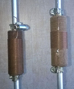
Vibrator of the shortened
dipole antenna made from aluminum tube in diameter of 8 mm. Lengthening
coil is installed at distance of 120 cm from the feeding terminals.
Coil form made of a textolite rod in
70 mm length and 15 mm diameter. The form has holes from
both sides where the aluminum tubes are inserted. Clamps installed
at the ends of tubes. Inductor wire is soldered to the clamp.
Coil for 20-m band wound with 1- mm (18- AWG) copper wire and
has 37 turns. Coil for 15- m band wound with 1- mm (18- AWG) copper
wire and has 16 turns. Kit for the 10 meter band
does not made because shortened antenna for 20 meter band as well
as shortened antenna for 15- meter band may be easily tuned to
the 10- meter with the help of automatic antenna tuner of the
transceiver. Figure 2
shows design of the lengthening coils. Antenna
installed outside of the balcony on L-Bracket. The bracket made
of a corner bead. Textolite plate in
6- mm width (it is used insulation plate from an electrical box)
is fixed on the end of the L- Bracket. Vibrators of the dipole
antenna is fastened to the insulation plate with help of metal
plates with sizes 50 x 50- mm. |
Figure 2 Design of the
Lengthening Coils |
||
|
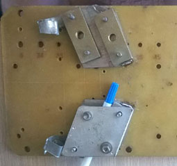
Gaskets
with a thickness of 8 mm (just the thickness of the aluminum tubes)
are placed between the plates. The plates fastened together with
help of screw in diameter of 4- mm. �Figure 3 shows the structure. Pen serves like
a part of the dipole antenna on the figure. Such design allows
fast to change one dipole antenna for another. Figure 4 shows dipole antenna with choke/balun on the textolite plate.
Figure 5
shows dipole antenna on the L-Bracket. Figure 6 shows dipole antenna on the balcony. Input impedance of the antenna, measured by antenna
analyzer MFJ- 259B, was 28 Ohm on 20- meter band and 28 Ohm on
15 meter band. Bandwidth was 40 kHz on 20 meter band and near
100 kHz on 15 meter band. Antenna for 20 meter band was fed through
a coaxial cable with length lambda/2 for the band. In this case
was good matching inside of the 20 meter band and automatic antenna
tuner of the transceiver could tune the antenna on the 15 and
10- meter bands. |
Figure 3 Structure of
the Fixing Antenna�s Vibrators�
on the Textolite Plate |
||
|
|
|||
|
|
Page- 19 |
||
 |
 |
|
 |
|
|
|||
Just for Fun:

Powered byIP2Location.com
Thanks for your time!
Last Updated:
October 16, 2019 17:00