


|
|
 |
 |
 |
|
|

Antentop is FREE e-magazine devoted to Antennas and Amateur Radio an
Special page devoted to
Design of Wide Band RF Transformer on Ferrite Tubes

Custom Search
|
ANTENTOP- 01- 2018 # 022 |
Design
of Wide Band RF Transformer on Ferrite Tubes |
|
|
|
|
The tubes are
fixed by Scotch. One such transformer could cover all HF Band
from 160 to 10 meter. The tubes have rounded edges. It eliminates
damage to the insulation of the winding wire by the edges. The article
described simplest transformers on binocular ferrite core with
separate primary and secondary winding. Table 1 shows data for the transformers. One turn is considered as a wire coming
through the holes of both sides of the binocular core. Half of
turn is considered as a wire coming through the hole of one side
of the binocular core. The
table shows that is possible create a
very wide range of the transformers for different resistance ratio. |
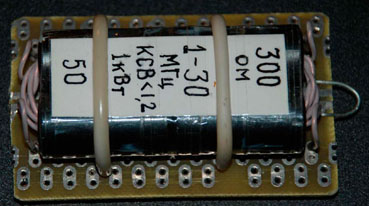
Practical
Design of Wide Band Transformer 300/50- Ohm, 1- 30- MHz |
|
A simplest
one, transformer with a 1: 1 ratio serves like a choke. This transformer
balances the RF current in the antenna parts (for symmetrical
antenna) and suppresses the common-mode current on the outer braid
of the coaxial cable. Other transformers in addition to this job
provide transformation of antenna impedance to impedance of the
feeding coaxial cable. What
should be guided when choosing the number of turns for primary
winding? With other things being equal, transformer with a single-turn
primary winding, compare to the double-turn primary winding counterpoint,
has about in four times higher lower frequency of the passband
together with the higher upper frequency of the passband. Therefore
for transformer used at 160 and 80 meter it is better to use double-turn
primary winding. For transformer used from 40 to 10 meter it is
better to use single-turn primary winding. The higher
is the transformation ratio the more difficult is to obtain a
wide bandwidth since the leakage inductance of the windings is
increased. The leakage inductance could be compensated by switching
on a capacitor in bridge to the primary winding. The capacity
of the capacitor should be found at minimum SWR at higher working
frequency of the transformer. The ready transformer could be tested. For the test the transformer
should be terminated to non- inductive resistor. Then SWR curve
should be taken at working range of the transformer. 73! de RU3ARJ |
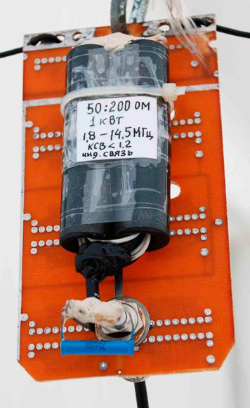
Practical
Design of Wide Band Transformer 200/50- Ohm, 1.8- 14.5- MHz with
compensation capacitor |
|
|
|
|
|
Page- 94 |
93 94
 |
 |
|
 |
|
|
|||
Just for Fun:

Powered byIP2Location.com
Thanks for your time!
Last Updated:
January 3, 2020 21:28